Jeep Liberty KJ. Manual - part 257


  Index      Jeep     Jeep Liberty KJ - service repair manual 2006 year


Search            


Content   ..  255  256  257  258   ..


Jeep Liberty KJ. Manual - part 257


When Monitored:
With the ignition on.

Set Condition:
If the Body Control Module (BCM) detects unwanted voltage on the (X3) Horn Relay Control circuit.

Possible Causes

HORN RELAY SHORTED

(X3) HORN RELAY CONTROL CIRCUIT SHORTED

BODY CONTROL MODULE (BCM)

Diagnostic Test

1.

VERIFY THAT THE DTC IS ACTIVE

Turn the ignition on.

With the scan tool, erase BCM DTCs.

With the scan tool, actuate the Horn Relay.

With the scan tool, read BCM DTCs.

Does the scan tool display: HORN RELAY OUTPUT HIGH?

Yes

>> Go To 2

No

>> The condition that caused this symptom is not currently present. Inspect the related wiring harness for

a possible intermittent condition. Look for any chafed, pierced, pinched or partially broken wires.

Perform BODY VERIFICATION TEST - VER 1. (Refer to 8 - ELECTRICAL/ELECTRONIC CONTROL
MODULES - STANDARD PROCEDURE).

2.

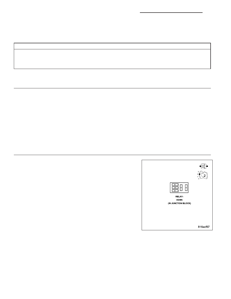
CHECK FOR A SHORTED HORN RELAY

Turn the ignition off.

Install a substitute Horn Relay in place of the existing relay.

Turn the ignition on.

With the scan tool, erase BCM DTCs.

With the scan tool, actuate the Horn Relay.

With the scan tool, read BCM DTCs.

Does the scan tool display: HORN RELAY OUTPUT HIGH?

Yes

>> Go To 3

No

>> Replace the original Horn Relay in accordance with the Ser-

vice Information.

Perform BODY VERIFICATION TEST - VER 1. (Refer to 8 -
ELECTRICAL/ELECTRONIC

CONTROL

MODULES

-

STANDARD PROCEDURE).

8Q - 4

VEHICLE THEFT SECURITY - ELECTRICAL DIAGNOSTICS

KJ

3.

CHECK FOR A SHORTED (X3) HORN RELAY CONTROL CIRCUIT

Turn the ignition off.

Remove the substitute Horn Relay from the Junction Block.

Remove the BCM from the Junction Block.

NOTE: Ensure that the Junction Block connectors are reconnected
at this time.
Turn the ignition on.

Measure the voltage of the (X3) Horn Relay Control circuit in the Horn
Relay connector in the Junction Block.

Is there any voltage present?

Yes

>> Replace the Junction Block in accordance with the Service

Information.

Perform BODY VERIFICATION TEST - VER 1. (Refer to 8 -
ELECTRICAL/ELECTRONIC

CONTROL

MODULES

-

STANDARD PROCEDURE).

No

>> Replace and program the BCM in accordance with the Ser-

vice Information.

Perform BODY VERIFICATION TEST - VER 1. (Refer to 8 - ELECTRICAL/ELECTRONIC CONTROL
MODULES - STANDARD PROCEDURE).

KJ

VEHICLE THEFT SECURITY - ELECTRICAL DIAGNOSTICS

8Q - 5

ITM–BCM MESSAGE NOT RECEIVED (EXPORT ONLY)

For a complete wiring diagram Refer to Section 8W

When Monitored:
When the Intrusion Transceiver Module (ITM) transmits bus messages.

Set Condition:
If the ITM fails to receive status messages from the Body Control Module (BCM).

Possible Causes

BUS COMMUNICATION FAILURE

INTRUSION TRANSCEIVER MODULE (ITM)

Diagnostic Test

1.

VERIFY THAT THE BCM IS ACTIVE ON THE BUS

Turn the ignition on.

With the scan tool, verify that the BCM is active on the bus.

Is the BCM active on the bus?

Yes

>> Go To 2

No

>> Refer to (Refer to 8 - ELECTRICAL/ELECTRONIC CONTROL MODULES - DIAGNOSIS AND TEST-

ING) for No Response related diagnostic procedures.

2.

VERIFY THAT THE DTC IS ACTIVE

With the scan tool, erase ITM DTCs.

Turn the ignition off.

Arm the VTSS and wait one minute.

Disarm the VTSS and turn the ignition on.

With the scan tool, read ITM DTCs.

Did this DTC reset?

Yes

>> Replace the ITM in accordance with the service information.

Perform BODY VERIFICATION TEST - VER 1. (Refer to 8 - ELECTRICAL/ELECTRONIC CONTROL
MODULES - STANDARD PROCEDURE).

No

>> The condition that caused this symptom is currently not present. Inspect the related wiring harness for

a possible intermittent condition. Look for any chafed, pierced or partially broken wires.

Perform BODY VERIFICATION TEST - VER 1. (Refer to 8 - ELECTRICAL/ELECTRONIC CONTROL
MODULES - STANDARD PROCEDURE).

8Q - 6

VEHICLE THEFT SECURITY - ELECTRICAL DIAGNOSTICS

KJ

ITM–EEPROM FAILURE (EXPORT ONLY)

For a complete wiring diagram Refer to Section 8W

When Monitored:
Continuously while the VTSS is armed and during change of the VTSS state.

Set Condition:
If the EEPROM erase/write does not correctly complete the operation.

Possible Causes

INTRUSION TRANSCEIVER MODULE (ITM)

Diagnostic Test

1.

VERIFY THAT THE DTC IS ACTIVE

Turn the ignition on.

With the scan tool, erase the ITM DTCs.

Turn the ignition off.

Arm the VTSS and wait one minute.

Disarm the VTSS and turn the ignition on.

With the scan tool, read ITM DTCs.

Did this DTC reset?

Yes

>> Replace the ITM in accordance with the Service Information.

Perform BODY VERIFICATION TEST - VER 1. (Refer to 8 - ELECTRICAL/ELECTRONIC CONTROL
MODULES - STANDARD PROCEDURE).

No

>> The condition that caused this symptom is currently not present. Test complete.

Perform BODY VERIFICATION TEST - VER 1. (Refer to 8 - ELECTRICAL/ELECTRONIC CONTROL
MODULES - STANDARD PROCEDURE).

KJ

VEHICLE THEFT SECURITY - ELECTRICAL DIAGNOSTICS

8Q - 7


Content   ..  255  256  257  258   ..