Jeep Liberty KJ. Manual - part 1317


  Index      Jeep     Jeep Liberty KJ - service repair manual 2006 year


Search            


Content   ..  1315  1316  1317  1318   ..


Jeep Liberty KJ. Manual - part 1317


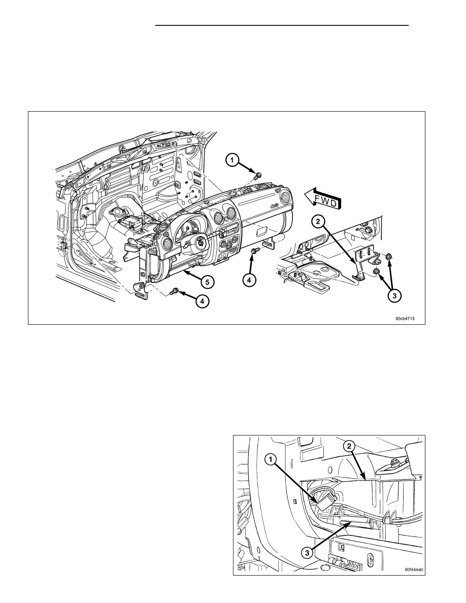
38. Roll the instrument panel rearward and remove the wire harness from routing channel in the rear.

39. Disconnect the push pin fastener and position aside the radio wire harness. Note the location of the harness for

installation.

40. Remove the instrument panel.

INSTALLATION

1. Before proceeding with the following repair procedure, review all warnings and cautions. (Refer to 23 - BODY/

INSTRUMENT PANEL - WARNING)

2. Position the instrument panel into the vehicle.

3. Position the wire harness into the rear routing channel and roll the instrument panel back against the cowl.

4. Position the radio wire harness and seat the push pin fastener.

NOTE: Position the speaker wires through the speaker openings.

5. Install the four bolts at the top of the instrument panel connecting to the cowl front panel and tighten to 28 N·m

(21 ft. lbs.).

6. Connect the blend door electrical connector.

7. Connect the blower motor electrical connector.

23 - 168

INSTRUMENT PANEL

KJ

8. Connect the vacuum check valve and the vacuum

reservoir.

9. Connect the blower resister electrical connector.

NOTE: Do not push or pull bracket. Tighten at the rest position.

10. Install the two roll down bracket bolts at the passenger cowl side panel and tighten to 54 N·m (40 ft. lbs.).

KJ

INSTRUMENT PANEL

23 - 169

11. Install the HVAC mounting bolt at the lower out-

side corner of the glove box opening and tighten
to 6 N·m (55 in. lbs.).

12. Install the HVAC mounting bolt above the glove

box striker.

13. Install the passenger side trim bezel. (Refer to 23

-

BODY/INSTRUMENT

PANEL/INSTRUMENT

PANEL PASSENGER SIDE BEZEL - INSTALLA-
TION)

14. Install the passenger side cowl trim cover. (Refer

to 23 - BODY/INTERIOR/COWL TRIM COVER -
INSTALLATION)

15. Install the two HVAC mounting bolts behind the

center trim.

16. Install the glove box. (Refer to 23 - BODY/IN-

STRUMENT PANEL/GLOVE BOX - INSTALLA-
TION)

23 - 170

INSTRUMENT PANEL

KJ

NOTE: Do not push or pull bracket. Tighten at the rest position.

17. Install the two roll down bracket bolts at the driver’s cowl side panel and tighten to 54 N·m (40 ft. lbs.).

18. Install the two bolts at the bottom side of the

pedal support bracket (3).

19. Install the two bolts (2) at the front of the pedal

support bracket.

20. Connect the electrical connector at the inner side

of the pedal support bracket.

KJ

INSTRUMENT PANEL

23 - 171


Content   ..  1315  1316  1317  1318   ..