Content .. 1105 1106 1107 1108 ..
Jeep Liberty KJ. Manual - part 1107
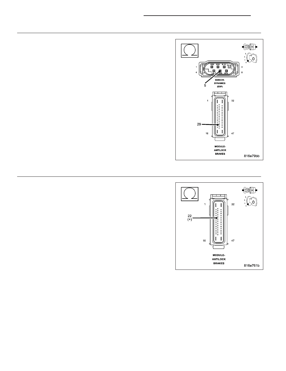
5.
CHECK (G94) DYNAMICS SENSOR GROUND CIRCUIT FOR HIGH RESISTANCE
Measure the resistance of the (G94) Dynamics Sensor Ground circuit
between the Dynamics Sensor harness connector and the Anti-Lock
Brakes Module harness connector.
Is the resistance below 5.0 ohms?
Yes
>> Go To 6
No
>> Repair the (G94) Dynamics Sensor Ground circuit for high
resistance.
Perform ABS VERIFICATION TEST - VER 1. (Refer to 5 -
BRAKES - STANDARD PROCEDURE).
6.
CHECK (G4) DYNAMICS SENSOR SUPPLY CIRCUIT FOR A SHORT TO OTHER ABS CIRCUITS
Measure the resistance between the (G4) Dynamics Sensor Supply cir-
cuit and the B46, B15, D21, D65, D64, Z127, D52, D51, G94, B6, B7,
B4. B3, B1, B2, B9, B8, and Z107 circuit in the Anti-Lock Brakes Mod-
ule harness connector.
Is the resistance below 10k ohms on any of the circuits?
Yes
>> Repair all circuits with a resistance below 10k ohms for a
short to the (G4) Dynamics Sensor Supply circuit.
Perform ABS VERIFICATION TEST - VER 1. (Refer to 5 -
BRAKES - STANDARD PROCEDURE).
No
>> Replace the Anti-Lock Brakes Module in accordance with
the Service Information.
Perform ABS VERIFICATION TEST - VER 1. (Refer to 5 -
BRAKES - STANDARD PROCEDURE).
5 - 188
BRAKES - ABS ELECTRICAL DIAGNOSTICS
KJ