Jeep Liberty KJ. Manual - part 1047


  Index      Jeep     Jeep Liberty KJ - service repair manual 2006 year


Search            


Content   ..  1045  1046  1047  1048   ..


Jeep Liberty KJ. Manual - part 1047


2.

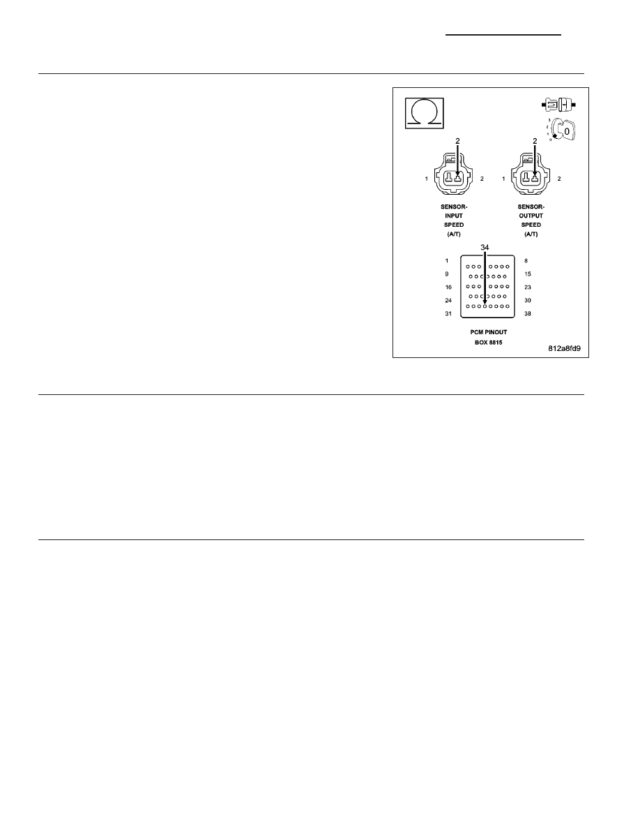
(T13) SPEED SENSOR GROUND CIRCUIT OPEN

Turn the ignition off to the lock position.

Disconnect the PCM C4 harness connector.

Disconnect the Input and Output Speed Sensor harness connectors.

NOTE: Check connectors - Clean/repair as necessary.

CAUTION: Do not probe the PCM harness connectors. Probing the
PCM harness connectors will damage the PCM terminals resulting
in poor terminal to pin connection. Install Miller Special Tool #8815
to perform diagnosis.
Measure the resistance of both of the (T13) Speed Sensor Ground cir-
cuits from the appropriate terminal of special tool #8815 to the Input
and Output Speed Sensor harness connectors.

Is the resistance above 5.0 ohms on either circuit?

Yes

>> Repair the (T13) Speed Sensor Ground circuit for an open.

Perform 42RLE TRANSMISSION VERIFICATION TEST -
VER 1. (Refer to 21 - TRANSMISSION/TRANSAXLE/AU-
TOMATIC - 42RLE - STANDARD PROCEDURE)

No

>> Go To 3

3.

POWERTRAIN CONTROL MODULE

Using the schematics as a guide, inspect the wiring and connectors. Repair as necessary. Pay particular attention
to all power and ground circuits.

If there are no possible causes remaining, view repair.

Repair

Replace and program the Powertrain Control Module per the Service Information. With the scan tool
perform QUICK LEARN.

Perform 42RLE TRANSMISSION VERIFICATION TEST - VER 1. (Refer to 21 - TRANSMISSION/
TRANSAXLE/AUTOMATIC - 42RLE - STANDARD PROCEDURE)

4.

INTERMITTENT WIRING AND CONNECTORS

The conditions necessary to set the DTC are not present at this time.

Using the schematics as a guide, inspect the wiring and connectors specific to this circuit.

Wiggle the wires while checking for shorted and open circuits.

With the scan tool, check the DTC EVENT DATA to help identify the conditions in which the DTC was set.

Were there any problems found?

Yes

>> Repair as necessary.

Perform 42RLE TRANSMISSION VERIFICATION TEST - VER 1. (Refer to 21 - TRANSMISSION/
TRANSAXLE/AUTOMATIC - 42RLE - STANDARD PROCEDURE)

No

>> Test Complete.

21 - 232

AUTOMATIC TRANSMISSION 42RLE - ELECTRICAL DIAGNOSTICS

KJ

P1797-MANUAL SHIFT OVERHEAT

For a complete wiring diagram Refer to Section 8W.

When Monitored:
Continuously with engine running.

Set Condition:
If the Engine Temperature exceeds 123° C (255° F) or the Transmission Temperature exceeds 135° C (275° F)
while in AutoStick

T

mode. Note: Aggressive driving or driving in low for extended periods of time will set this

DTC.

Possible Causes

MANUAL SHIFT OVERHEAT

Always perform the 42RLE Pre-Diagnostic Troubleshooting procedure before proceeding. (Refer to 21 -
TRANSMISSION/TRANSAXLE/AUTOMATIC - 42RLE - STANDARD PROCEDURE)

Theory of Operation

The major cause of heat build up in the transmission is torque converter slip. With the transmission in the Auto-
Stick

T

mode, the torque converter can slip during aggressive driving or heavy loading conditions such as trailer

towing or driving up steep grades. In the non AutoStick

T

mode, internal controller logic prevents the transmission

from overheating by managing the shift and EMCC schedule. In the AutoStick

T

mode, when the transmission or

engine temperature approaches an overheat condition, the manual shift overheat DTC sets and the AutoStick

T

mode is temporarily suspended until the temperature returns to normal.

Diagnostic Test

1.

MANUAL SHIFT OVERHEAT

This is an informational DTC only.

With the scan tool, check the DTC EVENT DATA to help identify the conditions in which the DTC was set.

Check the engine and transmission cooling system for proper operation.

Check the Radiator Cooling Fan operation.

Check the Transmission Cooling operation.

Check the Transmission Fluid Level per the Service Information to verify that it is not overfilled.

NOTE: Aggressive driving or driving in low for extended periods of time will set this DTC.

If there are no possible causes remaining, view repair.

Repair

If the Transmission Fluid is low, repair any Transmission Fluid leak as necessary and adjust the Trans-
mission Fluid Level per the Service Information. Refer to Service Information for the related symptoms
and repair as necessary.

Perform 42RLE TRANSMISSION VERIFICATION TEST - VER 1. (Refer to 21 - TRANSMISSION/
TRANSAXLE/AUTOMATIC - 42RLE - STANDARD PROCEDURE)

U0100 LOST COMMUNICATION WITH ECM/PCM

For a complete wiring diagram Refer to Section 8W.

KJ

AUTOMATIC TRANSMISSION 42RLE - ELECTRICAL DIAGNOSTICS

21 - 233

When Monitored:
Every 7 msec with:
1) Engine speed greater than 500 RPM.
2) Battery voltage between 10 and 16 volts.

Set Condition:
CAN C bus messages are not received for 10 seconds.

Theory of Operation

The NGC controller communicates over the CAN C bus. The transmission controller continuously monitors bus
activity. The CAN C bus is also used to communicate transmission MIL status to the Engine Controller. If the Engine
Controller is unable to communicate with the Transmission Controller, a DTC will set and the Engine Controller will
illuminate the MIL.

(Refer to 8 - ELECTRICAL/ELECTRONIC CONTROL MODULES - DIAGNOSIS AND TESTING) for diagnostic
procedures and for further possible causes.

U0002–CAN C BUS OFF PERFORMANCE

For a complete wiring diagram Refer to Section 8W.

When Monitored:
With the ignition on.

Set Condition:
If the Anti-Lock Brakes Module detects a short in either CAN C Bus circuit.

Perform CAN C Bus Communication Failure diagnostic test procedure. (Refer to 8 - ELECTRICAL/ELECTRONIC
CONTROL MODULES - DIAGNOSIS AND TESTING)
.

U0121 LOST COMMUNICATION WITH ABS

For a complete wiring diagram Refer to Section 8W.

When Monitored:
Every 7 msec with:
1) Engine speed greater than 500 RPM.
2) Battery voltage between 10 and 16 volts.

Set Condition:
CAN C bus messages are not received for 10 seconds.

Theory of Operation

The NGC controller communicates over the CAN C bus. The transmission controller continuously monitors bus
activity. The CAN C bus is also used to communicate transmission MIL status to the Engine Controller. If the Engine
Controller is unable to communicate with the Transmission Controller, a DTC will set and the Engine Controller will
illuminate the MIL.

(Refer to 8 - ELECTRICAL/ELECTRONIC CONTROL MODULES - DIAGNOSIS AND TESTING) for diagnostic
procedures and for further possible causes.

STANDARD PROCEDURE

21 - 234

AUTOMATIC TRANSMISSION 42RLE - ELECTRICAL DIAGNOSTICS

KJ

PRE-DIAGNOSTIC TROUBLESHOOTING PROCEDURE - 42RLE

For a complete wiring diagram Refer to Section 8W.

1.

Perform the following steps prior to any diagnostic procedure:

Many transmission symptoms can be caused by a low fluid level. If the fluid level is low, locate and repair any
leaks and fill the transmission to the proper fluid level. Refer to the Service Information for the proper repair
and fluid fill procedures.

Testing should only be performed with the battery fully charged to avoid false diagnosis.

With the scan tool, read Engine (PCM) DTCs. If Engine DTCs are present, refer to the Driveability Category
and perform to the appropriate diagnostic procedure(s) before proceeding.

With the scan tool, read Transmission (TCM) DTCs. Record all Stored, Active, and Pending DTC information.
Diagnose any Pending DTC as a matured DTC.

With the scan tool, read DTC EVENT DATA. Use this data to identify the conditions in which the DTC was set.

NOTE: Performing a Battery Disconnect will clear all DTC EVENT DATA and reset all learned Transmission
values to the controllers default values, which may temporarily result in erratic shift schedules.

With the scan tool, perform the Shift Lever Position Test. If the test does not pass, refer to the diagnostic
procedure for P0706-Check Shifter Signal.

For Gear Ratio Error DTCs, use the scan tool to read and record the Clutch Volume Index (CVI) information.

Use the wiring diagram as a guide, inspect the wiring and connectors related to this circuit and repair as nec-
essary.

Refer to the When Monitored and Set Conditions for this DTC. DTCs can set at ignition on, at start up, driving
under specific conditions, and after controller diagnostic monitors have run.

Refer to applicable Technical Service Bulletins (TSBs) for controller software update information. Some condi-
tions can be corrected by upgrading the Engine (PCM) or Transmission (TCM) controller software.

Check for any Service Information Tune-ups or Service Bulletins for any possible causes that may apply.

Were there any repairs made that fixed the vehicle?

Yes

>> Testing complete.

Perform 42RLE VERIFICATION TEST - VER 1 (Refer to 21 - TRANSMISSION/TRANSAXLE/AUTO-
MATIC - 42RLE - STANDARD PROCEDURE)

No

>> Refer to the Transmission category and perform the appropriate diagnostic procedure(s). (Refer to 21 -

TRANSMISSION/TRANSAXLE/AUTOMATIC - 42RLE - DIAGNOSIS AND TESTING)

KJ

AUTOMATIC TRANSMISSION 42RLE - ELECTRICAL DIAGNOSTICS

21 - 235


Content   ..  1045  1046  1047  1048   ..