Jeep Grand Cherokee WK. Manual - part 716


  Index      Jeep     Jeep Grand Cherokee WK - service repair manual 2005 year


Search            


Content   ..  714  715  716  717   ..


Jeep Grand Cherokee WK. Manual - part 716


B1412-HFM LEFT AUDIO OUTPUT CIRCUIT HIGH (CONTINUED)

4.

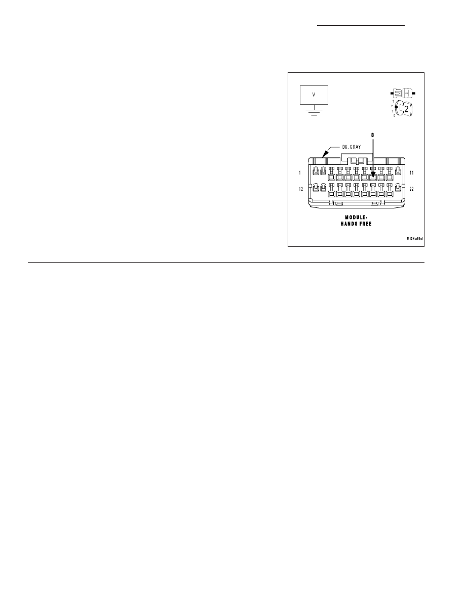
(X703) LEFT AUDIO OUTPUT CIRCUIT SHORT TO VOLTAGE

Turn the ignition on.

Measure the voltage of the (X703) Left Audio Output circuit.

Is the voltage above 1.0 volts?

Yes

>> Repair the (X703) Left Audio Output circuit for a short to

voltage.

Perform BODY VERIFICATION TEST – VER 1. (Refer to 8
- ELECTRICAL/ELECTRONIC CONTROL MODULES -
STANDARD PROCEDURE).

No

>> Inspect the wiring and connectors for damage or shorted

circuits. If ok, replace and program the Hands Free Mod-
ule in accordance with the service information.

Perform BODY VERIFICATION TEST – VER 1. (Refer to 8
- ELECTRICAL/ELECTRONIC CONTROL MODULES -
STANDARD PROCEDURE).

8T - 10

NAVIGATION/TELECOMMUNICATION - ELECTRICAL DIAGNOSTICS

WK

B1415-HFM RIGHT AUDIO OUTPUT CIRCUIT LOW

WK

NAVIGATION/TELECOMMUNICATION - ELECTRICAL DIAGNOSTICS

8T - 11

B1415-HFM RIGHT AUDIO OUTPUT CIRCUIT LOW (CONTINUED)

For a complete wiring diagram Refer to Section 8W.

When Monitored:
With the ignition on.

Set Condition:
The Hands Free Module detects low voltage on the (X704) Right Audio Output circuit.

Possible Causes

(X704) RIGHT AUDIO OUTPUT CIRCUIT OPEN

(X704) RIGHT AUDIO OUTPUT CIRCUIT SHORT TO GROUND

(X795) COMMON AUDIO OUTPUT CIRCUIT OPEN

(X704) RIGHT AUDIO OUTPUT CIRCUIT SHORT TO (X795) COMMON AUDIO OUTPUT CIRCUIT

HANDS FREE MODULE

Diagnostic Test

1.

CHECK FOR ACTIVE DTC

With the scan tool, read the active DTC’s.

Cycle the ignition switch from off to on at least 5 times, leaving the ignition on for a minimum of 90 seconds per
cycle.

With the scan tool, read the active DTC’s.

Does the scan tool display this DTC as active?

Yes

>> Go To 2

No

>> If the DTC is stored, check for an intermittent condition. Visually inspect the related wiring harness con-

nectors. Look for broken, bent, pushed out, or corroded terminals.

8T - 12

NAVIGATION/TELECOMMUNICATION - ELECTRICAL DIAGNOSTICS

WK

B1415-HFM RIGHT AUDIO OUTPUT CIRCUIT LOW (CONTINUED)

2.

(X704) RIGHT AUDIO OUTPUT CIRCUIT OPEN

Turn the ignition off.

Disconnect the Hands Free Module harness connector.

Disconnect the Radio C1 harness connector.

Measure the resistance of the (X704) Right Audio Output circuit
between the HFM connector and the radio connector.

Is the resistance below 5.0 ohms?

Yes

>> Go To 3

No

>> Repair the (X704) Right Audio Output circuit for an open.

Perform BODY VERIFICATION TEST – VER 1. (Refer to 8
- ELECTRICAL/ELECTRONIC CONTROL MODULES -
STANDARD PROCEDURE).

3.

(X704) RIGHT AUDIO OUTPUT CIRCUIT SHORT TO GROUND

Measure the resistance between ground and the (X704) Right Audio
Output circuit.

Is the resistance below 5.0 ohms?

Yes

>> Repair the (X704) Right Audio Output circuit for short to

ground.

Perform BODY VERIFICATION TEST – VER 1. (Refer to 8
- ELECTRICAL/ELECTRONIC CONTROL MODULES -
STANDARD PROCEDURE).

No

>> Go To 4

WK

NAVIGATION/TELECOMMUNICATION - ELECTRICAL DIAGNOSTICS

8T - 13


Content   ..  714  715  716  717   ..