Jeep Grand Cherokee WK. Manual - part 670


  Index      Jeep     Jeep Grand Cherokee WK - service repair manual 2005 year


Search            


Content   ..  668  669  670  671   ..


Jeep Grand Cherokee WK. Manual - part 670


Depressing the OFF switch

Depressing the CANCEL switch.

The speed control can be disengaged also by any of the following conditions:

An indication of Park or Neutral (auto. trans.)

The VSS signal increases at a rate of 10 mph per second (indicates that the co-efficient of friction between the
road surface and tires is extremely low)

Depressing the clutch pedal (manual trans.).

Excessive engine rpm (indicates that the transmission may be in a low gear)

The VSS signal decreases at a rate of 10 mph per second (indicates that the vehicle may have decelerated at
an extremely high rate)

If the actual speed is not within 20 mph of the set speed

The previous disengagement conditions are programmed for added safety.

Once the speed control has been disengaged, depressing the ACCEL switch restores the vehicle to the target
speed that was stored in the PCM’s RAM

NOTE: Depressing the OFF switch will erase the set speed stored in the PCM’s RAM.

If, while the speed control is engaged, the driver wishes to increase vehicle speed, the PCM is programmed for an
acceleration feature. With the ACCEL switch held closed, the vehicle accelerates slowly to the desired speed. The
new target speed is stored in the PCM’s RAM when the ACCEL switch is released. The PCM also has a

9

tap-up

9

feature in which vehicle speed increases at a rate of approximately 2 mph for each momentary switch activation of
the ACCEL switch.

The PCM also provides a means to decelerate without disengaging speed control. To decelerate from an existing
recorded target speed, depress and hold the COAST switch until the desired speed is reached. Then release the
switch. The ON, OFF switch operates two components: the PCM’s ON, OFF input, and the battery voltage to the
brake switch.

REMOVAL

WARNING: BEFORE ATTEMPTING TO DIAGNOSE,
REMOVE OR INSTALL ANY AIRBAG SYSTEM OR
RELATED

STEERING

WHEEL

AND

STEERING

COLUMN COMPONENTS YOU MUST FIRST DIS-
CONNECT

AND

ISOLATE

THE

NEGATIVE

(GROUND) BATTERY CABLE. WAIT 2 MINUTES
FOR

SYSTEM

CAPACITOR

TO

DISCHARGE

BEFORE FURTHER SYSTEM SERVICE. FAILURE
TO DO SO COULD RESULT IN ACCIDENTAL
DEPLOYMENT

AND

POSSIBLE

PERSONAL

INJURY.

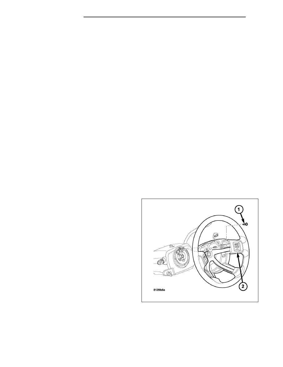
1. Disconnect and isolate negative battery cable from

battery.

2. Remove airbag module. Refer to Restraint Sys-

tems.

3. Unplug electrical connector.

4. Remove speed control switch mounting screw (1)

and remove switch from steering wheel.

8P - 12

SPEED CONTROL

WK

INSTALLATION

1. Position switch (2) to steering wheel.

2. Install switch mounting screw (1) and tighten. Refer

to torque specifications.

3. Plug electrical connector into switch.

4. Install airbag module. Refer to Restraint Systems.

5. Connect negative battery cable to battery.

RESERVOIR-VACUUM

DESCRIPTION

1 - Air Cleaner Box
2 - Vacuum Line
3 - Speed Control Servo
4 - Cross Support
5 - Electrical. Connector
6 - Servo Mounting Bracket
7 - Servo Mounting Bolt
8 - Vacuum Reservoir Mounting Bolt
9 - Vacuum Reservoir

WK

SPEED CONTROL

8P - 13

The vacuum reservoir is a plastic storage tank connected to an engine vacuum source by vacuum lines.

The reservoir (9) is attached to the side of the air cleaner filter housing (1).

A vacuum reservoir is not used with diesel engines or the 5.7L gas powered engine.

OPERATION

The vacuum reservoir is used to supply the vacuum needed to maintain proper speed control operation when
engine vacuum drops, such as in climbing a grade while driving. A one-way check valve is used in the vacuum line
between the reservoir and the vacuum source. This check valve is used to trap engine vacuum in the reservoir. On
certain vehicle applications, this reservoir is shared with the heating/air-conditioning system. The vacuum reservoir
cannot be repaired and must be replaced if faulty.

DIAGNOSIS AND TESTING - VACUUM RESERVOIR

Refer to Diagnosis and Testing — Vacuum Supply Test for procedures.

REMOVAL

The vacuum reservoir (9) is attached to the side of the air cleaner filter housing (1).

1. Disconnect vacuum line (2) at reservoir.

2. Remove reservoir mounting bolt (8).

3. Remove reservoir (9).

1 - Air Cleaner Box
2 - Vacuum Line
3 - Speed Control Servo
4 - Cross Support
5 - Electrical. Connector
6 - Servo Mounting Bracket
7 - Servo Mounting Bolt
8 - Vacuum Reservoir Mounting Bolt
9 - Vacuum Reservoir

8P - 14

SPEED CONTROL

WK

INSTALLATION

1. Position reservoir (9) to air filter housing.

2. Install and tighten mounting bolt (8).

3. Connect vacuum line (2) to reservoir fitting.

1 - Air Cleaner Box
2 - Vacuum Line
3 - Speed Control Servo
4 - Cross Support
5 - Electrical. Connector
6 - Servo Mounting Bracket
7 - Servo Mounting Bolt
8 - Vacuum Reservoir Mounting Bolt
9 - Vacuum Reservoir

WK

SPEED CONTROL

8P - 15


Content   ..  668  669  670  671   ..