Jeep Grand Cherokee WK. Manual - part 450


  Index      Jeep     Jeep Grand Cherokee WK - service repair manual 2005 year


Search            


Content   ..  448  449  450  451   ..


Jeep Grand Cherokee WK. Manual - part 450


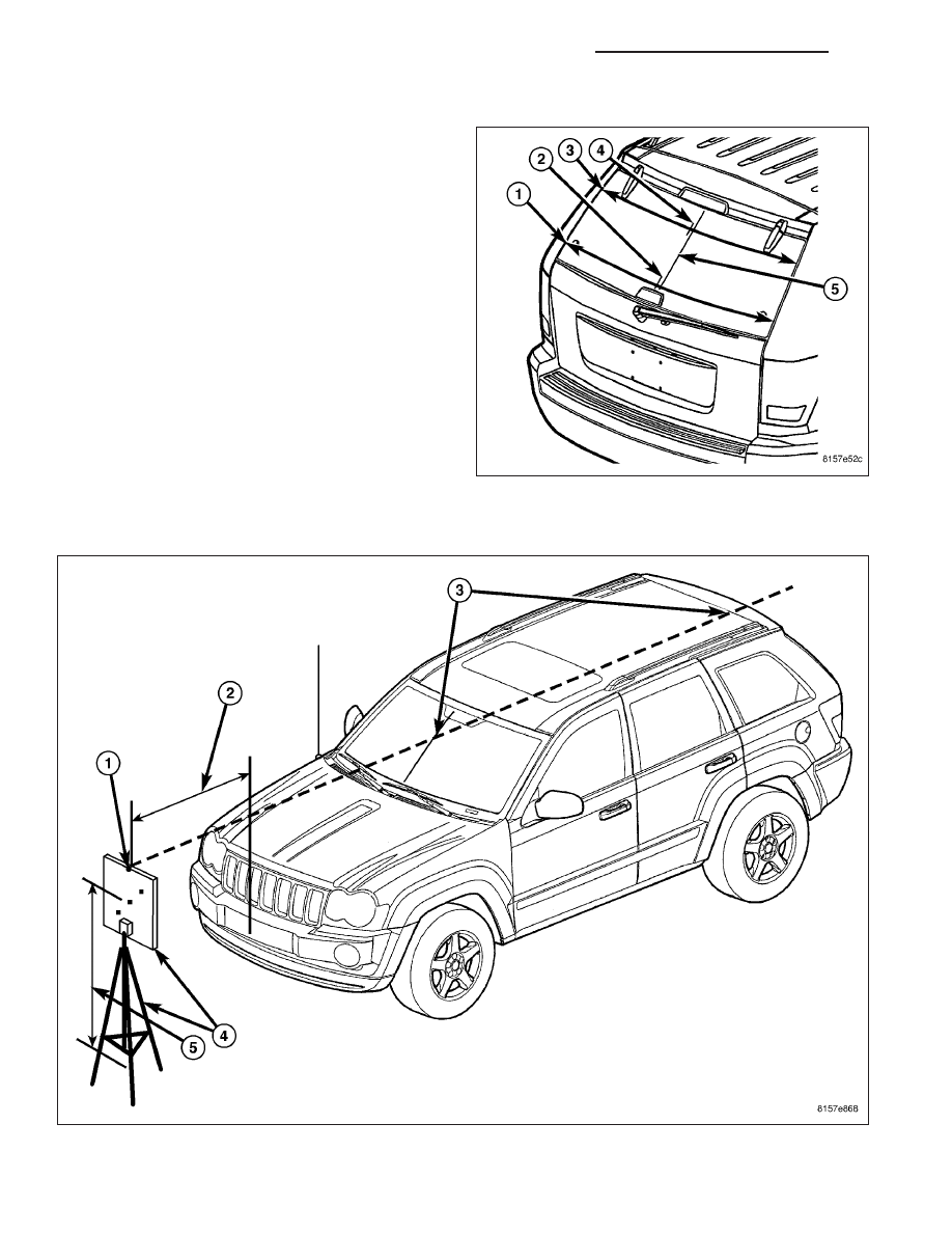
MARK IMAGER CENTERLINE ON LIFTGATE GLASS

1. Take a measurement (3) across the lower edge of

the liftgate glass hinges using the vertical edges of
the body liftgate opening as the reference points.

2. Divide the upper measurement in half and mark

that dimension on the glass (4) using a grease
pencil. This is the upper centerline of the glass.

3. Take a measurement (1) across the lower edge of

the liftgate glass strut mounts using the vertical
edges of the body liftgate opening as the reference
points.

4. Divide the lower measurement in half and mark

that dimension on the glass (2) using a grease
pencil. This is the lower centerline of the glass.

5. Measure and mark 21 millimeters (0.827 inches)

toward the passenger side of the liftgate glass from
the upper and lower glass centerline marks and
draw a line (5) between these marks. This is the
centerline of the imager.

SET UP AIM BOARD AND TRIPOD

1. Position the vehicle on a level surface in a dimly lit area.

2. Place the aim board and tripod (4) (Special Tool #9649) 127 centimeters (50 inches) ahead of the foremost cen-

ter of the front fascia (2).

8L - 110

LAMPS/LIGHTING - EXTERIOR - SERVICE INFORMATION

WK

3. Sight through the V-notch (1) in the upper edge of the aim board to align and center the board to the imager

centerline marks on both the windshield and the liftgate glass (3).

4. Adjust the tripod so that the center Light Emitting Diode (LED) on the aim board is 145 centimeters (57 inches)

from the level floor (5).

CALIBRATION PROCEDURE

1. For re-calibration of a previously calibrated mirror,

connect a diagnostic scan tool to the Data Link
Connector (DLC) (1) below the driver side end of
the instrument panel (2).

2. Turn the ignition switch to the On position.

3. A new mirror will begin flashing the electrochromic

LED at a rate of once-per-second to indicate that it
is in calibration mode and calibration is required.
For re-calibration of a previously calibrated mirror,
use the diagnostic scan tool to enter the Smart-
Beam unit into calibration mode. Look in the diag-
nostic

scan

tool

under

the

“SmartBeam”

or

“Automatic High Beam Module/AHBM” menu item
as

appropriate.

When

a

previously

calibrated

SmartBeam unit has entered calibration mode, it
will also be indicated by flashing the electrochromic
LED at a rate of once-per-second.

4. Connect the aim board transformer to illuminate the

aim board LED units. The electrochromic LED will
continue to flash for five to ten seconds, then will stop flashing to indicate that it has completed calibration. If the
LED begins to flash at a faster rate (twice-per-second), it indicates that a Diagnostic Trouble Code (DTC) has
been recorded. Use the diagnostic scan tool to retrieve the DTC, then refer to the appropriate diagnostic
information.

SMARTBEAM DEMONSTRATION MODE

The SmartBeam automatic high beam system has a demonstration mode. This mode allows the function of the
automatic high beams accompanied with that of the high beam indicator in the instrument cluster to be demon-
strated while the vehicle is stationary and under any ambient lighting conditions. Besides demonstrating the auto-
matic high beam system, this mode will confirm that the system electronics and circuitry are functional. This mode
also incorporates a feature that allows a functional test of the imager optics to be performed.

NOTE: The SmartBeam Demonstration Mode will NOT be functional when a diagnostic scan tool is con-
nected to the 16-way Data Link Connector (DLC) beneath the instrument panel on the driver side. Once the
demonstration sequence has begun, a detected vehicle speed input of over 8 kilometers-per-hour (5 miles-
per-hour) will cause the sequence to be aborted and the automatic high beam system to return to normal
operation.

1. With the ignition switch in the Off position, depress and hold depressed the “Auto” button on the electrochromic

inside rear view mirror.

2. With the “Auto” button still depressed, turn the ignition switch to the On position.

3. Continue to hold the “Auto” button depressed until the Demonstration Mode begins (headlamp high beams and

high beam indicator illuminate), at which time the button may be released.

4. The automatic high beam system will complete three cycles of ramping up the headlamp high beams to full

brightness, then ramping them down until fully extinguished accompanied by the appropriate indications from the
high beam indicator. At the conclusion of this sequence (about 40 seconds), the automatic high beam system will
return to normal operation.

WK

LAMPS/LIGHTING - EXTERIOR - SERVICE INFORMATION

8L - 111

IMAGER OPTICS TEST

If the green Light Emitting Diode (LED) located on the electrochromic inside rear view mirror just to the left of the
“Auto” button does not flash on and off several times when the ignition switch is turned to the On position, but the
automatic high beam system is not operating as it should, the SmartBeam imager optics may be dirty or obstructed.
The optics of the imager may be tested while the automatic high beam system is in the Demonstration Mode. This
test will confirm that the imager can “see” ambient light through the imager lens and the windshield. If the LED does
flash when the ignition switch is turned to the On position, (Refer to 8 - ELECTRICAL/LAMPS/LIGHTING - EXTE-
RIOR - DIAGNOSIS AND TESTING - SMARTBEAM).

1. Begin by initiating the automatic high beam Demonstration Mode.

2. Observe the green LED located on the electrochromic inside rear view mirror just to the left of the “Auto” button.

3. Obstruct the view of the imager by placing a hand or another suitable obstruction between the imager lens and

the windshield, or over the windshield glass in front of the imager. The LED should extinguish each time the
optics are obstructed, then illuminate again each time the obstruction is removed.

4. Failure of the LED to respond to these inputs indicates that the imager optics are obstructed.

CAUTION: Do not spray glass cleaners directly onto the imager lens. Damage to the imager optics and elec-
tronics may result.

5. Clean the imager lens and the windshield glass and/or remove any obstructions from the windshield in front of

the imager. To clean the imager lens, spray a small amount of glass cleaner onto a soft cloth and gently wipe the
lens clean.

6. Repeat the test to confirm proper automatic high beam imager operation.

SWITCH-STOP LAMP

DESCRIPTION

The brake lamp switch is mounted on a bracket
attached to the brake pedal support. The switch is
adjustable.

OPERATION

The brake lamp switch is used for the brake lamp, speed control and brake sensor circuits.

8L - 112

LAMPS/LIGHTING - EXTERIOR - SERVICE INFORMATION

WK

REMOVAL

1. Disconnect and isolate the battery negative cable.

2. Remove the steering column cover and lower trim

panel.

3. Press the brake pedal downward to fully applied

position.

4. Rotate the switch approximately 30° in counter-

clockwise direction to unlock the switch retainer.
Pull switch rearward and out of bracket.

5. Disconnect switch harness and remove switch from

vehicle.

INSTALLATION

1. Pull the switch plunger all the way out to fully

extended position.

2. Connect the harness wires (1) to switch.

3. Press and hold brake pedal in applied position.

4. Install the switch (3) as follows: Align the tab on the

switch with the notch in the switch bracket. Insert
the switch in the bracket and turn it clockwise
about 30° to lock it in place.

5. Release the brake pedal. Then pull the pedal lightly

rearward. The pedal will set the plunger to the cor-
rect position as the pedal pushes the plunger into
switch body. The switch will make ratcheting sound
as it self adjusts.

CAUTION: Booster damage may occur if the pedal
pull exceeds 20 lbs.

ADJUSTMENTS

SWITCH-STOP LAMP

1. Press and hold brake pedal in applied position.

2. Pull switch plunger all the way out to fully extended position.

3. Release brake pedal. Then pull pedal lightly rearward. Pedal will set plunger to correct position as pedal pushes

plunger into switch body. Switch will make ratcheting sound as it self adjusts.

WK

LAMPS/LIGHTING - EXTERIOR - SERVICE INFORMATION

8L - 113


Content   ..  448  449  450  451   ..