Jeep Grand Cherokee WK. Manual - part 371
5.7L
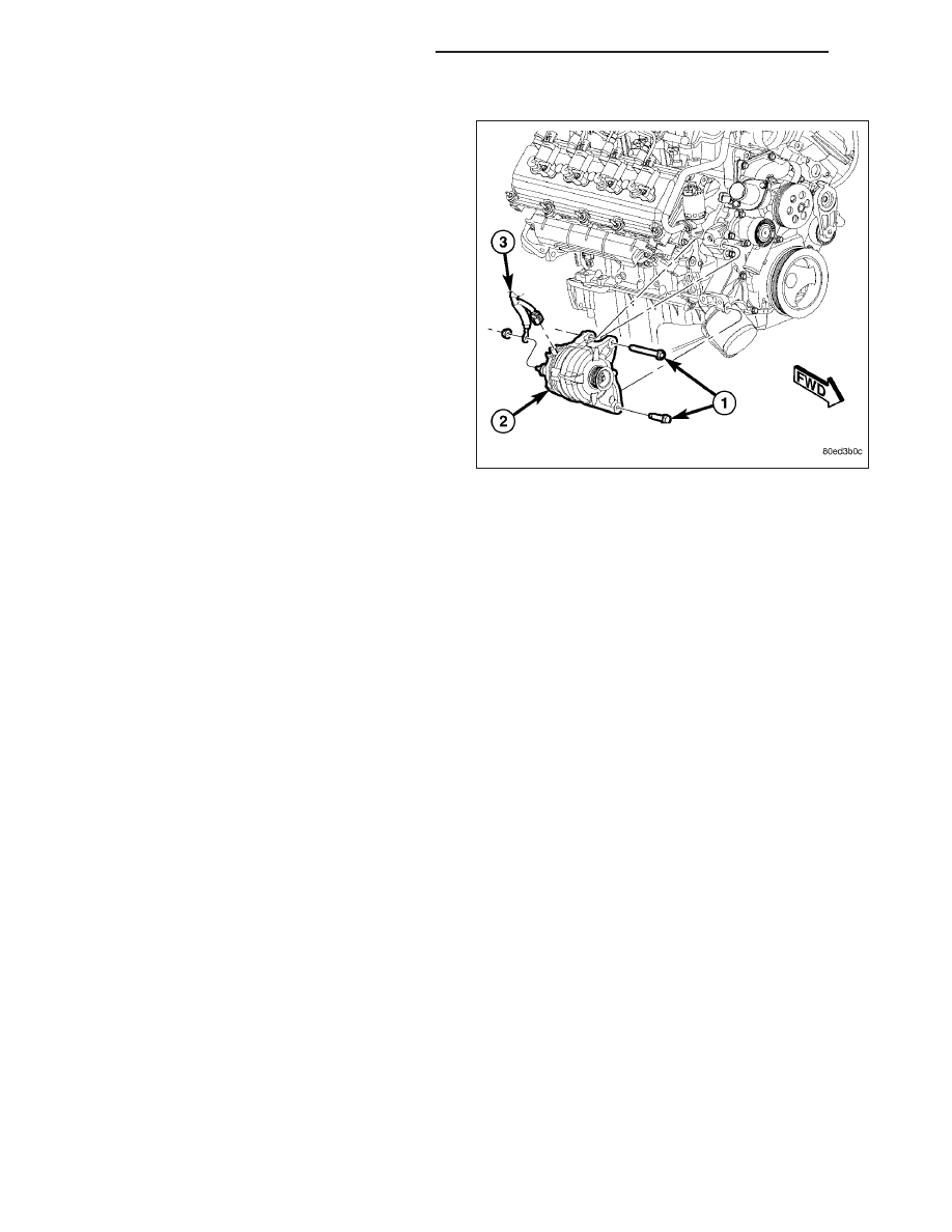
1. Position generator (2) to engine and install 2
mounting bolts (1).
2. Tighten bolts. Refer to Torque Specifications.
3. Snap field wire connector (3) into rear of generator.
4. Install B+ terminal eyelet (3) to generator output
stud. Tighten mounting nut. Refer to Torque Speci-
fications.
CAUTION: Never force a belt over a pulley rim
using a screwdriver. The synthetic fiber of the belt
can be damaged.
CAUTION: When installing a serpentine accessory
drive belt, the belt MUST be routed correctly. The
water pump may be rotating in the wrong direction
if the belt is installed incorrectly, causing the
engine to overheat. Refer to belt routing label in
engine compartment, or refer to Belt Schematics
in 7, Cooling System.
5. Install generator drive belt. Refer to 7, Cooling System for procedure.
6. Install negative battery cable to battery.
REGULATOR, VOLTAGE
DESCRIPTION
The Electronic Voltage Regulator (EVR) is not a separate component. It is actually a voltage regulating circuit
located within the Powertrain Control Module (PCM). The EVR is not serviced separately. If replacement is neces-
sary, the PCM must be replaced.
OPERATION
The amount of DC current produced by the generator is controlled by EVR circuitry contained within the PCM. This
circuitry is connected in series with the generators second rotor field terminal and its ground.
Voltage is regulated by cycling the battery voltage to control the strength of the rotor magnetic field. The EVR cir-
cuitry monitors system line voltage (B+) and battery temperature (refer to Battery Temperature Sensor for more
information). It then determines a target charging voltage. If sensed battery voltage is 0.5 volts or lower than the
target voltage, the PCM energizes the field winding until sensed battery voltage is 0.5 volts above target voltage. A
circuit in the PCM cycles the battery side of the generator field up to 100 times per second (100Hz), but has the
capability to full field to achieve the target voltage. If the charging rate cannot be monitored (limp-in), a duty cycle
of 25% is used by the PCM in order to have some generator output.
8F - 36
CHARGING - SERVICE INFORMATION
WK