Jeep Grand Cherokee WK. Manual - part 1671


  Index      Jeep     Jeep Grand Cherokee WK - service repair manual 2005 year


Search            


Content   ..  1669  1670  1671  1672   ..


Jeep Grand Cherokee WK. Manual - part 1671


32–EVAPORATOR SENSOR SHORTED (MTC) (CONTINUED)

2.

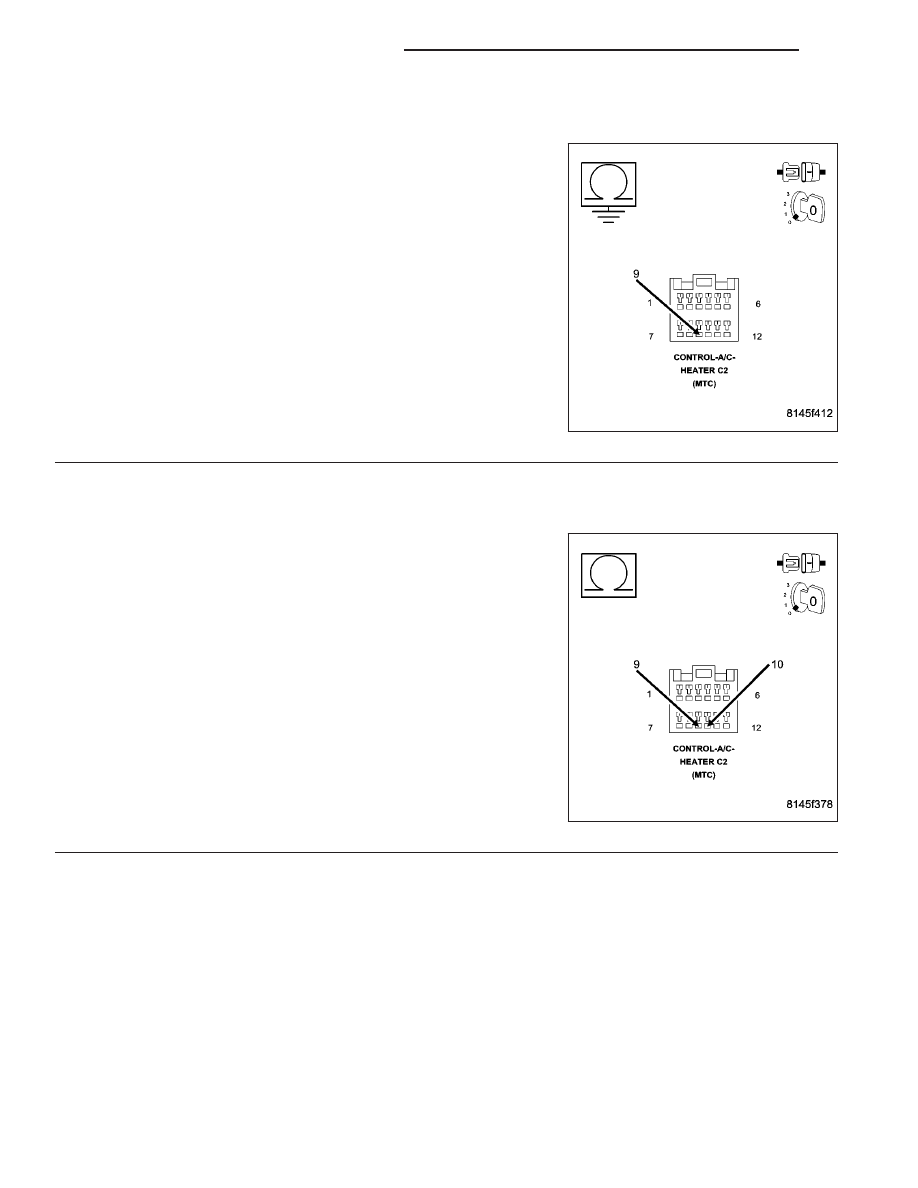
CHECK (C21) EVAPORATOR TEMPERATURE SENSOR SIGNAL CIRCUIT FOR A SHORT TO GROUND

Turn the ignition off.

Disconnect the A/C Heater Control C2 harness connector.

Measure the resistance of the (C21) Evaporator Temperature Sensor
Signal circuit between ground and the A/C Heater Control C2 harness
connector.

Is the resistance below 10k ohms?

Yes

>> Repair the (C21) Evaporator Temperature Sensor Signal

circuit for a short to ground.

Perform BODY VERIFICATION TEST – VER 1. (Refer to 8
- ELECTRICAL/ELECTRONIC CONTROL MODULES -
STANDARD PROCEDURE).

No

>> Go To 3

3.

CHECK (C21) EVAPORATOR TEMPERATURE SENSOR SIGNAL CIRCUIT FOR A SHORT TO (C121)
SENSOR GROUND CIRCUIT

Measure the resistance between the (C21) Evaporator Temperature
Sensor Signal circuit and the (C121) Sensor Ground circuit in the A/C
Heater Control C2 harness connector.

Is the resistance below 10k ohms?

Yes

>> Repair the (C21) Evaporator Temperature Sensor Signal

circuit for a short to the (C121) Sensor Ground circuit.

Perform BODY VERIFICATION TEST – VER 1. (Refer to 8
- ELECTRICAL/ELECTRONIC CONTROL MODULES -
STANDARD PROCEDURE).

No

>> Replace the A/C Heater Control in accordance with the

Service Information.

Perform BODY VERIFICATION TEST – VER 1. (Refer to 8
- ELECTRICAL/ELECTRONIC CONTROL MODULES -
STANDARD PROCEDURE).

24 - 32

HVAC - ELECTRICAL DIAGNOSTICS

WK

33–A/C MODE SWITCH STUCK (MTC)

WK

HVAC - ELECTRICAL DIAGNOSTICS

24 - 33

33–A/C MODE SWITCH STUCK (MTC) (CONTINUED)

For a complete wiring diagram Refer to Section 8W.

Theory of Operation

The switch input changes when the switch is pushed down. A stored DTC 33 indicates that the A/C mode switch
was stuck in a pushed position for more than 10 minutes, but has since returned to its normal state. An active DTC
33 indicates that the A/C mode switch is stuck in a pushed position. An active DTC 33 will prevent the control from
entering diagnostic mode and performing certain diagnostic functions. It will also prevent proper A/C mode switch
and status indicator function. For additional information about the A/C Heater Control’s on-board diagnostics, refer to
24 - HEATING & AIR CONDITIONING - DIAGNOSIS AND TESTING.

When Monitored:
With the ignition on.

Set Condition:
If the A/C mode switch stays in a pushed position for more than 10 minutes.

Possible Causes

OBJECT HOLDING A/C MODE SWITCH IN A PUSHED POSITION

SUBSTANCE CAUSING A/C MODE SWITCH TO GET STUCK IN A PUSHED POSITION

(C41) BLOWER SWITCH POSITION SIGNAL CIRCUIT SHORTED TO VOLTAGE

(C41) BLOWER SWITCH POSITION SIGNAL CIRCUIT SHORTED TO (C121) SENSOR GROUND CIRCUIT

(C41) BLOWER SWITCH POSITION SIGNAL CIRCUIT SHORTED TO GROUND

(C41) BLOWER SWITCH POSITION SIGNAL CIRCUIT OPEN

A/C STATUS INDICATOR INOPERATIVE

A/C HEATER CONTROL

Diagnostic Test

1.

INSPECT THE A/C HEATER CONTROL FOR DAMAGE

Turn the ignition off.

Inspect the A/C Heater Control for damage.

Is the A/C Heater Control damaged?

Yes

>> Replace the A/C Heater Control in accordance with the Service Information.

Perform BODY VERIFICATION TEST – VER 1. (Refer to 8 - ELECTRICAL/ELECTRONIC CONTROL
MODULES - STANDARD PROCEDURE).

No

>> Go To 2

2.

INSPECT FOR OBJECT OR SUBSTANCE CAUSING THE A/C MODE SWITCH TO STAY OR STICK IN A
PUSHED POSITION

Inspect the A/C Heater Control for anything that would cause the A/C mode switch to stay or stick in a pushed
position.

Is anything present that would cause the A/C mode switch to stay or stick in a pushed position?

Yes

>> Repair as necessary.

Perform BODY VERIFICATION TEST – VER 1. (Refer to 8 - ELECTRICAL/ELECTRONIC CONTROL
MODULES - STANDARD PROCEDURE).

No

>> Go To 3

24 - 34

HVAC - ELECTRICAL DIAGNOSTICS

WK

33–A/C MODE SWITCH STUCK (MTC) (CONTINUED)

3.

CHECK THE (C41) BLOWER SWITCH POSITION SIGNAL CIRCUIT VOLTAGE

Disconnect the A/C Heater Control C3 harness connector.

Turn the ignition on.

Measure the voltage of the (C41) Blower Switch Position Signal circuit.

What is the voltage?

Below 4.8 Volts

Go To 4

Above 5.2 Volts

Go To 7

4.8 Volts To 5.2 Volts

Go To 8

4.

CHECK THE (C41) BLOWER SWITCH POSITION SIGNAL CIRCUIT FOR A SHORT TO THE (C121)
SENSOR GROUND CIRCUIT

Turn the ignition off.

Disconnect the A/C Heater Control C2 harness connector.

Measure the resistance between the (C41) Blower Switch Position Sig-
nal circuit and the (C121) Sensor Ground circuit in the A/C Heater
Control C2 harness connector.

Is the resistance below 10K ohms?

Yes

>> Repair the (C41) Blower Switch Position Signal circuit for

a short to the (C121) Sensor Ground circuit.

Perform BODY VERIFICATION TEST - VER 1. (Refer to 8
- ELECTRICAL/ELECTRONIC CONTROL MODULES -
STANDARD PROCEDURE).

No

>> Go To 5

WK

HVAC - ELECTRICAL DIAGNOSTICS

24 - 35


Content   ..  1669  1670  1671  1672   ..