Jeep Grand Cherokee WK. Manual - part 1273


  Index      Jeep     Jeep Grand Cherokee WK - service repair manual 2005 year


Search            


Content   ..  1271  1272  1273  1274   ..


Jeep Grand Cherokee WK. Manual - part 1273


5. Connect Adapter 8630-4 to the power steering gear.

6. Open the test valve completely.

7. Start engine and let idle long enough to circulate power steering fluid through the flow/pressure test gauge.

8. Shut off the engine and check the fluid level, add fluid ass necessary. Start engine again and let idle.

9. The initial pressure reading should be 345-552 kPa (50-80 psi). If pressure is higher inspect the hoses for restric-

tions and repair as necessary.

10. Increase the engine speed to 1500 RPM and read the flow meter. The reading should be 2.4 - 2.8 GPM if the

reading is below this specification the fan should be replaced.

CAUTION: This next step involves testing maximum fan motor steering relief pressure. Do not leave the
valve closed for more than three seconds.

11. Close the valve fully three times for three seconds and record highest pressures indicated each time. All three

readings must be at fan motor steering relief pressures.

12. Open the test valve and turn the steering wheel to the extreme left and right positions against the stops. Record

the highest pressure readings at each position. If pressure readings are not within 50 psi from each other, the
gear is leaking internally and must be repaired.
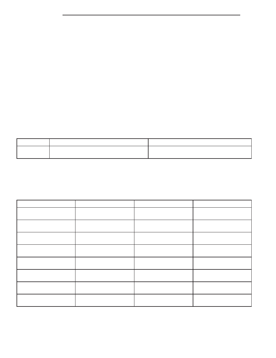
PUMP SPECIFICATIONS

ENGINE

RELIEF PRESSURE ± 50

FLOW RATE (GPM)

5.7L

1241 kPa (1800 psi)

1500 RPM 2.9 - 3.3 GPM Minium
@ 200 psi

SPECIFICATIONS

TORQUE CHART

TORQUE SPECIFICATIONS

DESCRIPTION

N·m

Ft. Lbs.

In. Lbs.

Pitman Arm

Shaft Nut

251

185

Drag Link

Pitman Arm Nut

88

65

Drag Link

Knuckle Nut

47

35

Drag Link

Clamp Nuts

41

30

Tie Rod

Knuckle Nut

47

35

Tie Rod

Clamp Nuts

41

30

Steering Damper

Axle Bolt

88

65

Steering Damper

Tie Rod Nut

41

30

19 - 6

STEERING

WK

SPECIAL TOOLS

STEERING LINKAGE

PULLER - 8677

ADAPTER, POWER STEERING FLOW/PRESSURE -

6825A

QUICK CONNECT TOOL - 8875-A

WK

STEERING

19 - 7

COLUMN - ELECTRICAL DIAGNOSTICS

TABLE OF CONTENTS

page

page

COLUMN - ELECTRICAL DIAGNOSTICS

DIAGNOSIS AND TESTING

C1240-STEERING ANGLE SENSOR ANGLE

OVERTRAVEL PERFORMANCE . . . . . . . . . . . . 9

C1219-STEERING ANGLE SENSOR

VELOCITY PERFORMANCE . . . . . . . . . . . . . . 11

B2225–STEERING ANGLE SENSOR

INTERNAL . . . . . . . . . . . . . . . . . . . . . . . . . . . 12

B2108–IGNITION SWITCH SENSE INPUT

CIRCUIT LOW . . . . . . . . . . . . . . . . . . . . . . . . 13

B2109–IGNITION SWITCH SENSE INPUT

CIRCUIT HIGH . . . . . . . . . . . . . . . . . . . . . . . . 15

B210D-BATTERY VOLTAGE LOW

. . . . . . . . . 17

B210E-BATTERY VOLTAGE HIGH

. . . . . . . . . 19

B2225–STEERING COLUMN MODULE

INTERNAL . . . . . . . . . . . . . . . . . . . . . . . . . . . 21

U0001–CAN C BUS

. . . . . . . . . . . . . . . . . . . . 22

U0021-CAN B BUS (+) CIRCUIT OPEN

. . . . . 25

U0022-CAN B BUS (+) CIRCUIT LOW

. . . . . . 25

U0023-CAN B BUS (+) CIRCUIT HIGH

. . . . . . 25

U0024-CAN B BUS (-) CIRCUIT OPEN

. . . . . . 25

U0025-CAN B BUS (-) CIRCUIT LOW

. . . . . . 25

U0026-CAN B BUS (-) CIRCUIT HIGH

. . . . . . 25

U0027-CAN B BUS (-) SHORTED TO BUS

(+) . . . . . . . . . . . . . . . . . . . . . . . . . . . . . . . . . 25

U0141–LOST COMMUNICATION WITH

FRONT CONTROL MODULE . . . . . . . . . . . . . 25

U0151-LOST COMMUNICATION WITH

OCCUPANT RESTRAINT CONTROLLER . . . . 25

U0154-LOST COMMUNICATION WITH

OCCUPANT CLASSIFICATION MODULE . . . . 26

U0155-LOST COMMUNICATION WITH

CLUSTER/CCN . . . . . . . . . . . . . . . . . . . . . . . 26

U0156-LOST COMMUNICATION WITH EOM

. 26

U0159-LOST COMMUNICATION WITH

PARKING ASSIST CONTROL MODULE . . . . . 26

U0164-LOST COMMUNICATION WITH HVAC

CONTROL MODULE . . . . . . . . . . . . . . . . . . . 26

U0167-LOST COMMUNICATION WITH

INTRUSION TRANSCEIVER CONTROL
MODULE . . . . . . . . . . . . . . . . . . . . . . . . . . . . 26

U0168-LOST COMMUNICATION WITH

VEHICLE SECURITY CONTROL MODULE
(SKREEM/WCM) . . . . . . . . . . . . . . . . . . . . . . 26

U0169-LOST COMMUNICATION WITH

SUNROOF CONTROL MODULE . . . . . . . . . . 26

U0184-LOST COMMUNICATION WITH

RADIO . . . . . . . . . . . . . . . . . . . . . . . . . . . . . . 26

U0186-LOST COMMUNICATION WITH

AUDIO AMPLIFIER . . . . . . . . . . . . . . . . . . . . . 27

U0195-LOST COMMUNICATION WITH

SDARS . . . . . . . . . . . . . . . . . . . . . . . . . . . . . 27

U0196-LOST COMMUNICATION WITH

VEHICLE ENTERTAINMENT CONTROL
MODULE . . . . . . . . . . . . . . . . . . . . . . . . . . . . 27

U0197-LOST COMMUNICATION WITH

HANDS FREE MODULE . . . . . . . . . . . . . . . . . 27

U0199-LOST COMMUNICATION WITH

DRIVER DOOR MODULE . . . . . . . . . . . . . . . . 27

U0200-LOST COMMUNICATION WITH

PASSENGER DOOR MODULE . . . . . . . . . . . . 27

U0208-LOST COMMUNICATION WITH

HEATED SEAT CONTROL MODULE . . . . . . . 27

U0209-LOST COMMUNICATION WITH

MEMORY SEAT CONTROL MODULE . . . . . . . 27

U0231-LOST COMMUNICATION WITH RAIN

SENSING MODULE . . . . . . . . . . . . . . . . . . . . 27

U0241-LOST COMMUNICATION WITH AUTO

HIGHBEAM HEADLAMP CONTROL
MODULE . . . . . . . . . . . . . . . . . . . . . . . . . . . . 28

COLUMN - ELECTRICAL DIAGNOSTICS

DIAGNOSIS AND TESTING

19 - 8

COLUMN - ELECTRICAL DIAGNOSTICS

WK

C1240-STEERING ANGLE SENSOR ANGLE OVERTRAVEL PERFORMANCE

For a complete wiring diagram Refer to Section 8W.

When Monitored:
Continuously.

Set Condition:
The Steering Column Module (SCM) has detected that the Steering Angle Sensor travel (rotation) has
exceeded 900 degrees.

Possible Causes

INTERMITTENT STEERING ANGLE SENSOR ANGLE OVERTRAVEL PERFORMANCE DTC

STEERING OR FRONT SUSPENSION COMPONENT DAMAGE

STEERING COLUMN MODULE (SCM)

Diagnostic Test

1.

DTC IS ACTIVE

NOTE: If B210D–BATTERY VOLTAGE LOW or B210E–BATTERY VOLTAGE HIGH is set along with this DTC,
diagnose the battery voltage DTC first.

Ignition on, engine not running.

Turn the steering wheel from stop to stop at least three times.

With the Scan Tool, select View DTCs in the Steering Column Module.

Is the DTC status Active at this time?

Yes

>> Go to 2

No

>> Go to 4

2.

STEERING OR FRONT SUSPENSION COMPONENT DAMAGE

Inspect the front suspension and steering components for damage or wear that may cause a steering column over-
travel condition.

Were any problems found?

Yes

>> Repair or replace front suspension or steering components as necessary in accordance with the Service

Information.

No

>> Go To 3

3.

STEERING COLUMN MODULE (SCM)

Remove the Steering Column Module in accordance with the Service Information. Inspect the steering column for
any problem that can result in a steering column overtravel condition. If any problems are found, repair as neces-
sary. If no problems are found, view repair.

Repair

Replace the Steering Column Module (SCM) in accordance with the Service Information.

WK

COLUMN - ELECTRICAL DIAGNOSTICS

19 - 9


Content   ..  1271  1272  1273  1274   ..