Jeep Grand Cherokee WK. Manual - part 1206


  Index      Jeep     Jeep Grand Cherokee WK - service repair manual 2005 year


Search            


Content   ..  1204  1205  1206  1207   ..


Jeep Grand Cherokee WK. Manual - part 1206


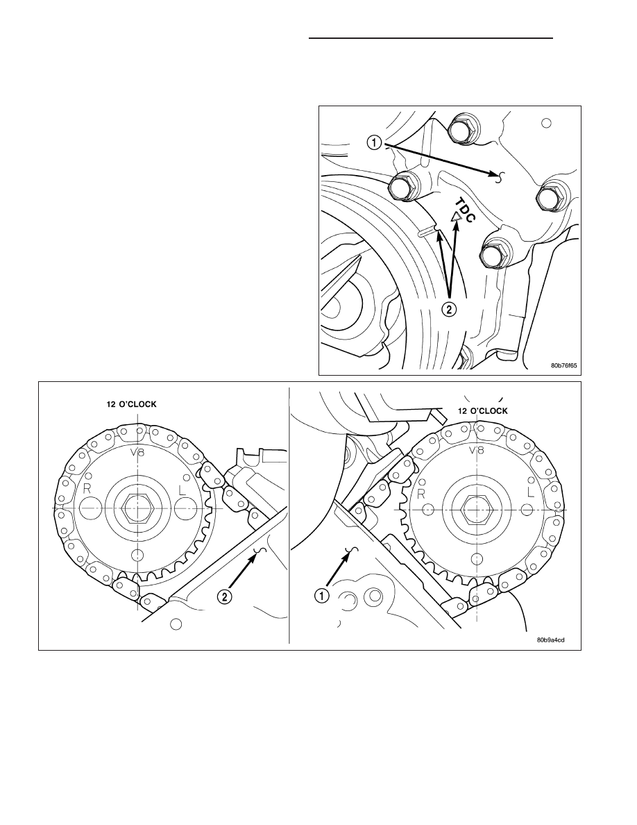
5. Rotate engine until timing mark on crankshaft damper aligns with TDC mark on timing chain cover (#1 cylinder

exhaust stroke) and the camshaft sprocket “V8” marks are at the 12 o’clock position.

6. Remove power steering pump.

7. Remove access plugs (2) from left and right cylin-

der heads for access to chain guide fasteners.

8. Remove the oil fill housing to gain access to the

right side tensioner arm fastener.

9 - 1420

ENGINE - 4.7L SERVICE INFORMATION

WK

9. Remove crankshaft damper (Refer to 9 - ENGINE/

ENGINE

BLOCK/VIBRATION

DAMPER

-

REMOVAL) and timing chain cover (Refer to 9 -
ENGINE/VALVE TIMING/TIMING BELT / CHAIN
COVER(S) - REMOVAL).

10. Collapse and pin primary chain tensioner.

CAUTION: Plate behind left secondary chain ten-
sioner could fall into oil pan. Therefore, cover pan
opening.

11. Remove secondary chain tensioners.

12. Remove camshaft position sensor from right cylin-

der head.

CAUTION: Care should be taken not to damage
camshaft target wheel. Do not hold target wheel
while loosening or tightening camshaft sprocket.
Do not place the target wheel near a magnetic
source of any kind. A damaged or magnetized tar-
get wheel could cause a vehicle no start condition.

CAUTION: Do not forcefully rotate the camshafts
or crankshaft independently of each other. Damag-
ing intake valve to piston contact will occur.
Ensure negative battery cable is disconnected to
guard against accidental starter engagement.

13. Remove left and right camshaft sprocket bolts.

14. While holding the left camshaft steel tube with

adjustable

pliers,

remove

the

left

camshaft

sprocket. Slowly rotate the camshaft approxi-
mately 15 degrees clockwise to a neutral position.

WK

ENGINE - 4.7L SERVICE INFORMATION

9 - 1421

15. While holding the right camshaft steel tube with

adjustable

pliers,

remove

the

right

camshaft

sprocket. Slowly rotate the camshaft approxi-
mately 45 degrees counterclockwise to a neutral
position.

16. Remove idler sprocket assembly bolt.

17. Slide the idler sprocket assembly and crank

sprocket forward simultaneously to remove the
primary and secondary chains.

18. Remove both pivoting tensioner arms and chain

guides.

19. Remove chain tensioner.

9 - 1422

ENGINE - 4.7L SERVICE INFORMATION

WK

INSPECTION

Inspect the following components:

Sprockets for excessive tooth wear. Some tooth markings are normal and not a cause for sprocket replace-
ment.

Idler sprocket assembly bushing and shaft for excessive wear.

Idler sprocket assembly spline joint. The joint should be tight with no backlash or axial movement.

Chain guides and tensioner arms. Replace these parts if grooving in plastic face is more than 1 mm (0.039 in.)
deep. If plastic face is severely grooved or melted, the tensioner lube jet may be clogged. The tensioner
should be replaced.

Secondary chain tensioner piston and ratcheting device. Inspect for evidence of heavy contact between ten-
sioner piston and tensioner arm. If this condition exist the tensioner and tensioner arm should be replaced.

Primary chain tensioner plastic faces. Replace as required.

INSTALLATION

1. Using a vise, lightly compress the secondary chain tensioner piston until the piston step is flush with the ten-

sioner body. Using a pin or suitable tool, release ratchet pawl by pulling pawl back against spring force through
access hole on side of tensioner. While continuing to hold pawl back, Push ratchet device to approximately 2 mm
from the tensioner body. Install Special Tool 8514 lock pin into hole on front of tensioner. Slowly open vise to
transfer piston spring force to lock pin.

WK

ENGINE - 4.7L SERVICE INFORMATION

9 - 1423


Content   ..  1204  1205  1206  1207   ..