Engine Iveco C10/C13/C78/Cursor 13/Cursor 78. Manual - part 86
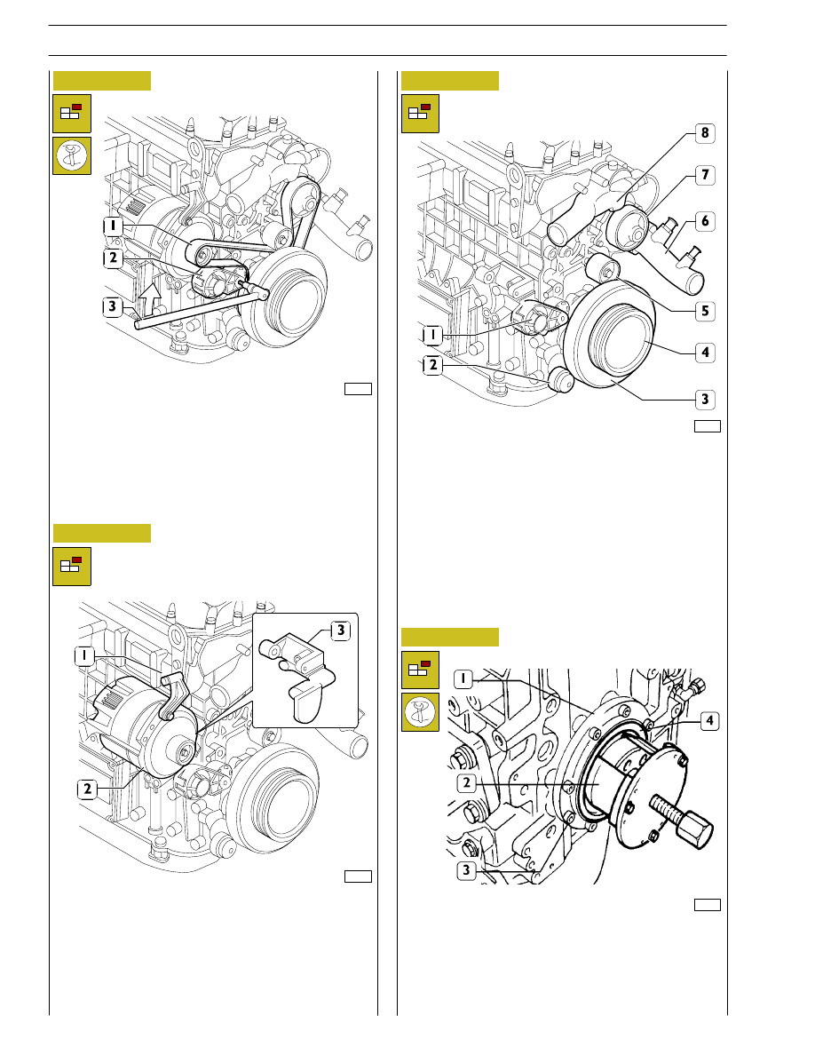
Figure 5
Figure 6
-
Using a suitable tool (3), work in the direction of the arrow
on the tightener (2) and remove the belt (1).
99359
Remove:
-
alternator (2).
-
supports (1 and 3).
99360
Figure 7
99256
Remove:
-
thermostat assembly (8);
-
pipes complete with coolant (6);
-
pulley (4);
-
water pump (7);
-
automatic tightener support (1);
-
fixed tightener (5);
-
damper flywheel (3) and pulley beneath;
-
automatic tightener (2);
Figure 8
With the extractor 99340053 (2) applied as shown in the
figure, extract the seal (4). Undo the screws (3) and take off
the cover (1). Disconnect all the electrical connections and
sensors.
99361
8
SECTION 3 - INDUSTRIAL APPLICATION