Isuzu Amigo / Axiom / Trooper / Rodeo / VehiCross. Manual - part 990


  Index      Isuzu     Isuzu Amigo / Axiom / Trooper / Rodeo / VehiCross - service repair manual 1999-2002 year


Search            


Content   ..  988  989  990  991   ..


Isuzu Amigo / Axiom / Trooper / Rodeo / VehiCross. Manual - part 990


8F–10

BODY STRUCTURE

General Description

This section includes items of front end sheet metal that
are attached by bolts, screws or clips and related
accessory components.
Anti-corrosion materials have been applied to the interior
surfaces of some metal panels to provide rust resistance.
When servicing these panels, areas on which this
material has been disturbed should be properly recoated
with service-type anti-corrosion material.
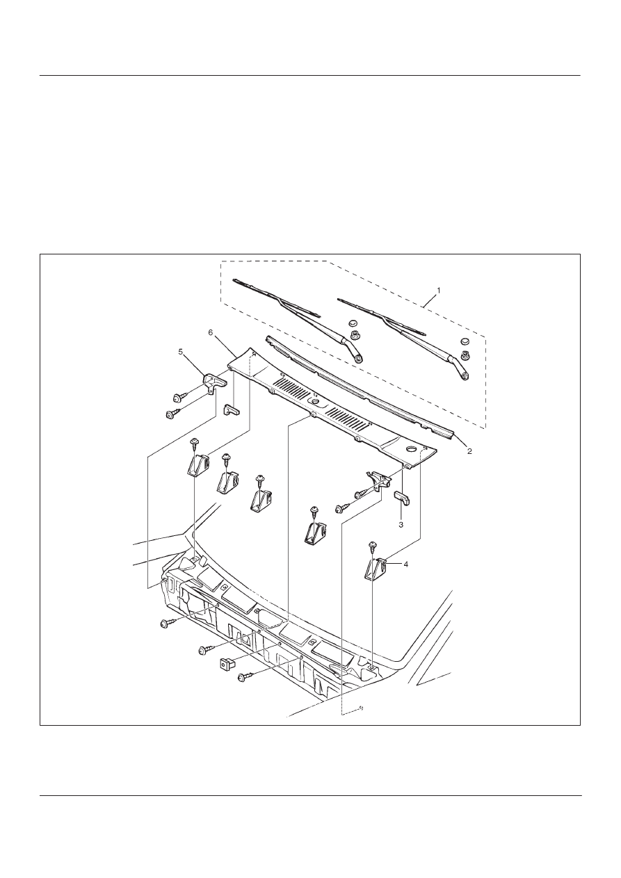
Cowl Cover

Parts Location

605R200002

Legend

(1) Front Wiper Arms
(2) Front Window Lower Molding
(3) Cowl Cover Seals

(4) Cowl Cover Stoppers
(5) Cowl Cover Brackets
(6) Cowl Cover

8F–11

BODY STRUCTURE

Removal

1. Open the hood.
2. Support the hood.
3. Remove front wiper arms.

D

Refer to Windshield Wiper Arm/Blade in
Wiper/Washer System section.

4. Remove front window lower molding.
5. Remove cowl cover brackets.

D

Disconnect two screws each side.

6. Remove cowl cover.

D

Disconnect three screws.

7. Remove cowl cover seals.
8. Remove cowl cover stoppers.

Installation

To install, follow the removal steps in reverse order.

Engine Hood

Removal

1. Open the hood.
2. Support the hood.
3. Remove windowshield washer nozzle tube.

880RS001

4. Remove hood hinge bolts (3).

D

Before removing the hinges from the Engine hood
(1), scribe a mark (2) showing location of the hinges
to facilitate installation in the original position.

610RS003

5. Remove engine hood.

Installation

To install, follow the removal steps in the reverse order
noting the following points:

1. Tighten the engine hood fixing bolts to the specified

torque.

Torque: 13 N

m (113 lb in)

2. Adjust the engine hood mounting gap with reference

to Body Dimension in this section.

3. Check and see if the engine hood lock operates

normally.

8F–12

BODY STRUCTURE

Engine Hood Hinge

Parts Location

610RW012

Legend

(1) Hinge Fixing Bolts And Nuts
(2) Hood End Seal

(3) Engine Hood Hinge
(4) Engine Hood
(5) Cowl Cover

Removal

1. Remove cowl cover.

D

 Refer to Cowl Cover in this section.

2. Remove engine hood.

D

Refer to Engine Hood in this section.

3. Remove hinge fixing bolt and nut.
4. Remove engine hood hinge.
5. Remove hood end seal.

Installation

To install, follow the removal steps in reverse order noting
the following points:

1. Tighten the hood hinge fixing bolt and nut to the

specified torque.

Torque 13  N

m (113 lb in)

8F–13

BODY STRUCTURE

Engine Hood Lock

Parts Location

610RY001

Legend

(1) Control Cable
(2) Hood Lock Control Lever

(3) Inner Liner
(4) Radiator Grille
(5) Engine Hood Lock Assembly

Removal

1. Remove hood lock control lever.
2. Remove inner liner.
3. Remove control cable.

D

Remove the cable fixing clips from the body panel.

4. Remove radiator grille.

D

Refer to Radiator Grille And Front End Lower Panel
in this section.

5. Remove engine hood lock assembly.

D

Apply setting marks (1) to the hood lock assembly
and the body prior to removal.

610RS002


Content   ..  988  989  990  991   ..