Isuzu Amigo / Axiom / Trooper / Rodeo / VehiCross. Manual - part 984
8D–36
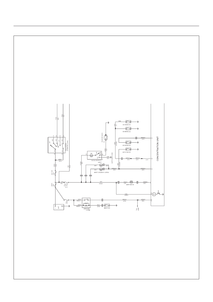
WIRING SYSTEM
Alarm and Relay Control Unit–1
D08R200232
Index Isuzu Isuzu Amigo / Axiom / Trooper / Rodeo / VehiCross - service repair manual 1999-2002 year
|
|
|
8D–36 WIRING SYSTEM Alarm and Relay Control Unit–1 D08R200232 |