Isuzu Amigo / Axiom / Trooper / Rodeo / VehiCross. Manual - part 960


  Index      Isuzu     Isuzu Amigo / Axiom / Trooper / Rodeo / VehiCross - service repair manual 1999-2002 year


Search            


Content   ..  958  959  960  961   ..


Isuzu Amigo / Axiom / Trooper / Rodeo / VehiCross. Manual - part 960


7C–10

CLUTCH

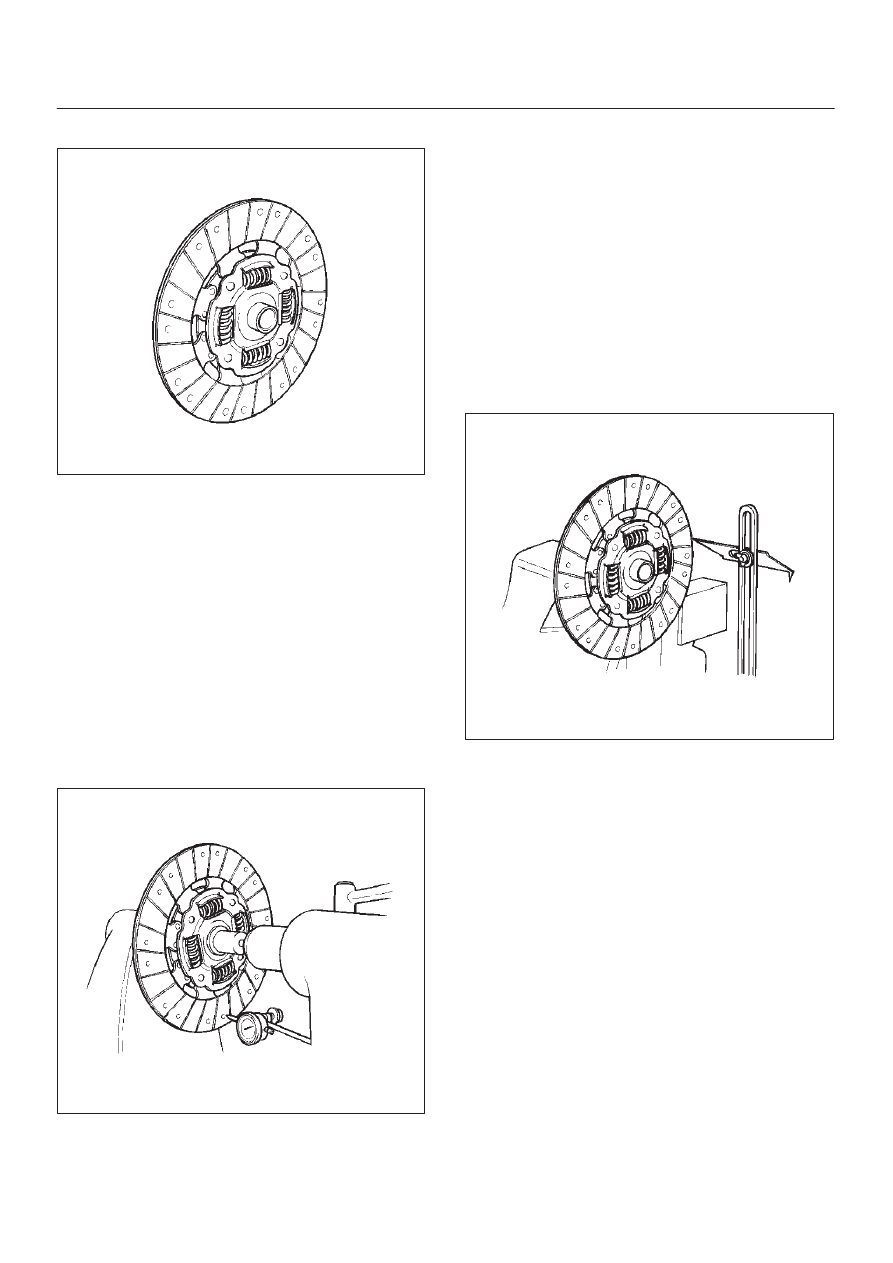
Driven Plate Assembly

201RS007

1. Visually check the torsion spring for looseness,

breakage, and weakening.

2. If any of these conditions are discovered, the driven

plate assembly must be replaced.

3. Visually check the facing surfaces for cracking and

excessive scorching.

4. Visually inspect the facing surfaces for the presence

of oil or grease.

5. If any of these conditions are discovered, the facing

must be cleaned or replaced.

6. Check that the driven plate moves smoothly on the

transmission top gear shaft spline.

7. Minor ridges on the top gear shaft spline may be

removed with an oil stone. 

Driven Plate Warpage

201RS008

1. Insert the clutch pilot aligner into the driven plate

splined hub.

2. The clutch pilot aligner J-24547 must be held

perfectly horizontal.

3. Set a dial indicator to the driven plate outside

circumference.

4. Slowly turn the driven plate.
5. Read the dial indicator as you turn the driven plate.
6. If the measured value exceeds the specified limit, the

driven plate assembly must be replaced. 

Driven Plate Warpage
Standard: 0.7 mm (0.028 in)
Limit: 1.0 mm (0.039 in)

Driven Plate Splined Hub Spline Wear

201RS009

1. Clean the driven plate splined hub.
2. Install the driven plate to the transmission top gear

shaft spline.

3. Set a surface gauge to the driven plate outside

circumference.

4. Slowly turn the driven plate counterclockwise.
5. Measure the spline rotation play as you turn the

driven plate.

6. If the measured value exceeds the specified limit, the

driven plate assembly must be replaced. 

Driven Plate Splined Hub Spline Wear 
Standard: 0.5 mm (0.020 in)
Limit: 1.0 mm (0.039 in)

CLUTCH

7C–11

Rivet Head Depression

201RS010

1. Use a depth gauge or a straight edge with steel rule to

measure the rivet head depression 1 from the facing
surface 2.

2. Be sure to measure the rivet head depression on both

sides of the driven plate.

3. If the measured value is less than the specified limit,

the driven plate assembly must be replaced.

Rivet Head Depression
Standard: 1.95 mm (0.077 in)
Limit: 0.2 mm (0.008 in)

Release Bearing 

201RS011

1. Visually check the release bearing for excessive play,

noise and breakage.

2. If any of these conditions are discovered, the release

bearing must be replaced.

3. When replacing the release bearing, replace both the

wedge collar and wire ring at the same time.

201RW010

Legend

(1) Wire Ring
(2) Pressure Plate Assembly
(3) Wedge Collar
(4) T/M Side
(5) Release Bearing
(6) Engine Side

Wedge Collar

201RS013

1. Visually check the surfaces of the wedge collar

making contact with the release bearing for excessive
wear and damage. 

2. Replace any exhibiting excessive wear or damage. 

7C–12

CLUTCH

Shift Fork 

201RS014

1. Visually check the surfaces of the shift fork making

contact with the release bearing for excessive wear
and damage.

2. Remove any minor stepping or abrasion from shift

fork with an oil stone.

3. Replace any exhibiting excessive wear or damage. 

Installation

To install, follow the removal steps in the reverse order,
noting the following points:

1. Install flywheel assembly and crankshaft bearing, use

the installer J-26516-A and driver handle J-8092 to
install the crankshaft bearing then clean and lubricate
with grease.

015RS046

2. Install new flywheel fixing bolts in the order illustrated

and tighten them to the specified torque.

Torque: 54 N·m (40 lb ft)

NOTE: Do not reuse the bolt and do not apply oil or thread
lock to the bolt. 

015RS047

3. Install the front cover (5) to the transmission case.
4. Tighten three fulcrum bridge bolts to the specified

torque.

Torque: 16.5 N·m (12 lb ft)

220RW088

5. Apply molybednum disulfide type grease to the pin

hole inner circumferences and thrust surfaces.

6. Attach the shift fork to the front cover and insert the

pin from below of the front cover.

CLUTCH

7C–13

7. Install the washer and snap pin. 

201RW019

8. Apply molybdenum disulfide type grease to the areas

shown in illustration.

201RW012

9. Install the release bearing in the proper direction. 

NOTE: Ensure release bearing is properly positioned
during installation, as shown in illustration. 

201RW020

10. Install driven plate assembly, use the pilot aligner

J-24547 to install the driven plate assembly. 

201RS016


Content   ..  958  959  960  961   ..