Isuzu Amigo / Axiom / Trooper / Rodeo / VehiCross. Manual - part 918


  Index      Isuzu     Isuzu Amigo / Axiom / Trooper / Rodeo / VehiCross - service repair manual 1999-2002 year


Search            


Content   ..  916  917  918  919   ..


Isuzu Amigo / Axiom / Trooper / Rodeo / VehiCross. Manual - part 918


7A–98

AUTOMATIC TRANSMISSION (4L30–E)

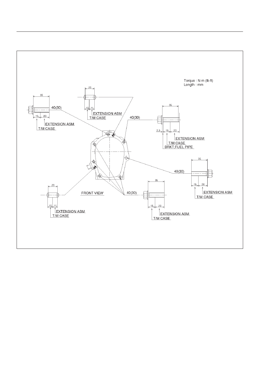
2. Install extension housing assembly (3) to the

transmission. Tighten extension housing assembly
bolts as shown in the figure.

261RY00001

3. Install speedometer driven gear bushing and driver

gear.

4. Connect harness connectors and fuel pipe fix bolt.

Connector: speed sensor.

5. Install propeller shaft (1) and mass (2).

Torque: 63 N·m (46 lb ft)

6. Fill extension housing assembly fluid.
7. Connect battery ground cable.

7A–99

AUTOMATIC TRANSMISSION (4L30–E)

Extension Housing Assembly

Extension Housing Assembly and Associated Parts

220RY00009

Legend

(1) Speedometer Sensor, Speedometer Driven

Gear and Plate

(2) Companion Flange
(3) Extension Housing Assembly

7A–100

AUTOMATIC TRANSMISSION (4L30–E)

Removal

1. Remove the speedometer sensor (1).
2. Remove the plate (1).
3. Remove the speedometer driven gear bushing and

driven gear (1).

NOTE: Apply a reference mark to the driven gear bushing
before removal.

4. Remove rear companion flange (2), using the flange

companion holder J–8614–11 to remove the end nut.

266RW001

5. Remove the rear companion flange.

NOTE: Use the universal puller to remove the rear
companion flange.

Installation

1. Install companion flange (2), using the companion

flange holder J–8614–11 to tighten the flange nuts to
the transfer case.

266RW001

2. Tighten the new transfer flange nuts to the specified

torque.

Torque
Companion flange: 167 N·m (123 lb ft)

3. Use the punch J–39209 to stake the companion

flange nut (3) at two spots.

266RS001

266RW002

7A–101

AUTOMATIC TRANSMISSION (4L30–E)

NOTE: Be sure to confirm that there is no crack at the
staked portion of the flange nut after staking.

4. Install the O–ring (7) to the speedometer driven gear

bushing (6).

5. Install the driven gear to the speedometer driven gear

bushing (6).

6. Install the speedometer driven gear assembly to the

extension housing assembly.

7. Install the plate (5) to the extension housing assembly

and tighten to the specified torque.

Torque: 15 N·m (11 lb ft)

8. Install the speedometer sensor and tighten to the

specified torque.

Torque: 27 N·m (20 lb ft)

225RY00003

Legend

(4) Bolt
(5) Plate
(6) Bushing
(7) O–ring


Content   ..  916  917  918  919   ..