Isuzu Amigo / Axiom / Trooper / Rodeo / VehiCross. Manual - part 917


  Index      Isuzu     Isuzu Amigo / Axiom / Trooper / Rodeo / VehiCross - service repair manual 1999-2002 year


Search            


Content   ..  915  916  917  918   ..


Isuzu Amigo / Axiom / Trooper / Rodeo / VehiCross. Manual - part 917


7A–94

AUTOMATIC TRANSMISSION (4L30–E)

Extension Housing Assembly Oil Seal

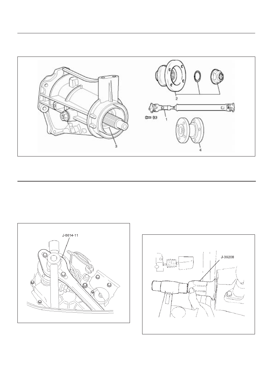
Extension Housing Assembly Rear Oil Seal and Associated Parts

220RY00010

Legend

(1) Propeller Shaft
(2) End Nut and Companion Flange

(3) Oil Seal
(4) Mass

Removal

1. Disconnect the propeller shaft (1) and mass (4) from

the extension housing assembly.

2. Remove end nut and companion flange (2), using the

companion flange holder J–8614–11.

266RW001

3. Use the universal puller to remove the companion

flange and O–ring.

4. Remove the oil seal from the extension housing

assembly.

Installation

1. Install oil seal and apply engine oil to the oil seal outer

surfaces.

2. Apply the recommended grease (BESCO L2) or

equivalent to the oil seal lip.

3. Use the oil seal installer J–39208 to install the rear

seal (3) to the extension housing assembly.

220RS016

7A–95

AUTOMATIC TRANSMISSION (4L30–E)

4. Install the companion flange (2) and O–ring (2).
5. Use the companion flange holder J–8614–11 to install

a new end nut (2) and tighten to the specified torque.

Torque: 167 N·m (123 lb ft)

6. Use the punch J–39209 to stake the end nut at two

spots.

NOTE: Be sure to confirm that there is no crack at the
staked portion of the end nut (2) after staking.

266RS001

266RW002

7. Connect the mass and propeller shaft to the

extension housing assembly and tighten to the
specified torque.

Torque: 63 N·m 46 (lb ft)

7A–96

AUTOMATIC TRANSMISSION (4L30–E)

Extension Housing Assembly

Extension Housing Assembly and Associated Parts

260RY00006

Legend

(1) Propeller Shaft

(2) Mass
(3) Extension Housing Assembly

7A–97

AUTOMATIC TRANSMISSION (4L30–E)

Removal

1. Disconnect battery ground cable.
2. Raise and support vehicle with suitable stands.
3. Disconnect harness connectors and fuel pipe fix bolt.

Connector: speed sensor.

4. Removing the speedometer driven gear bushing and

driven gear, drain extension housing assembly fluid.

5. Remove propeller shaft (1) and mass (2).

NOTE: Apply alignment marks on the flange at both front
and rear sides.

6. Remove extension housing assembly (3) from the

vehicle.

Installation

1. Apply a thin coat of molybdenum disulfide grease to

the extension shaft spline as shown in the figure.

260RY00004


Content   ..  915  916  917  918   ..