Isuzu Amigo / Axiom / Trooper / Rodeo / VehiCross. Manual - part 908


  Index      Isuzu     Isuzu Amigo / Axiom / Trooper / Rodeo / VehiCross - service repair manual 1999-2002 year


Search            


Content   ..  906  907  908  909   ..


Isuzu Amigo / Axiom / Trooper / Rodeo / VehiCross. Manual - part 908


7A–58

AUTOMATIC TRANSMISSION (4L30–E)

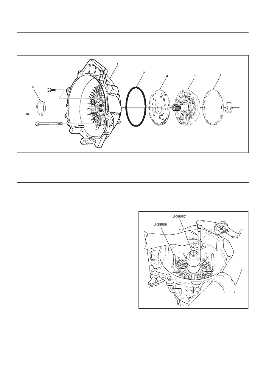
Converter Housing And Oil Pump Assembly

Disassembled View

241RY001

Legend

(1) Converter Housing
(2) Outer Seal Ring
(3) Gasket

(4) Wear Plate
(5) Oil Pump Assembly
(6) Oil Seal Ring

Disassembly

1. Remove oil pump assembly from converter housing. 
2. Remove outer seal ring. 
3. Remove gasket. 
4. Remove wear plate. 
5. Remove oil seal ring.

Inspection And Repair

Visual Check:

If any damage, deformation, or local wear is found in a
converter housing, outer seal ring, wear plate, or oil seal
ring, replace it.

Reassembly

1. Install wear plate onto oil pump assembly.
2. Install converter housing onto complete oil pump

assembly. Align with two short J–38588 guide pins on
outer bolt holes.

D

Loosely install five 13mm bolts.

D

Center converter housing using J–38557 centering
tool.

D

Tighten five inner 13mm bolts in an alternating
pattern.

Torque: 20 N

m (15 lb ft)

241RW002

3. Install oil seal ring (3 screws).

Torque: 3 N

m (26 lb in)

4. Install gasket. 
5. Install outer seal ring. 

7A–59

AUTOMATIC TRANSMISSION (4L30–E)

Oil Pump

Disassembled View

241RY002

Legend

(1) Oil Pump Drive Gear
(2) Oil Pump Driven Gear
(3) Pin
(4) Plug
(5) Seal Ring
(6) Torque Converter Clutch Control Valve
(7) Converter Clutch Control Valve Spring
(8) Pin
(9) Converter Clutch Regulator Sleeve

(10)

Converter Clutch Regulator Spring

(11)

Converter Clutch Regulator Valve

(12)

Isolator Spring

(13)

Isolator Valve

(14)

Pin

(15)

Enable Valve Spring Guide

(16)

Enable Valve Spring

(17)

Enable Valve

(18)

Snap Ring

(19)

Spring Seat

(20)

Throttle Signal Accumulator Spring

(21)

Throttle Signal Accumulator Piston

(22)

Sleeve Pin

(23)

Boost Valve Sleeve

(24)

Boost Valve

(25)

Spring Seat

(26)

Pressure Regulator Valve Spring

(27)

Spring Seat

(28)

Pressure Regulator Valve

(29)

Oil Pump Assembly

Disassembly

1. Remove oil pump drive gear (1) and driven gear (2).
2. Remove pin (3) from oil pump assembly (29).
3. Remove plug (4) and seal ring (5), torque converter

clutch control valve (6) and spring (7).

4. Remove pin (8) from oil pump assembly (29).

5. Remove torque converter regulator sleeve (9),

converter clutch regulator spring (10), converter
clutch regulator valve (11), isolator spring (12) and
isolator valve (13).

6. Remove pin (14) from oil pump assembly (29).
7. Remove enable valve spring (16), spring guide (15)

and enable valve (17).

8. Remove snap ring (18) from oil pump assembly (29).

7A–60

AUTOMATIC TRANSMISSION (4L30–E)

9. Remove spring seat (19), spring (20) and throttle

signal accumulator piston (21).

10. Remove sleeve pin (22) from oil pump assembly (29).

11. Remove boost valve sleeve (23), boost valve (24),

spring seat (25), valve spring (26), spring seat (27),
and pressure regulator valve (28).

Inspection And Repair

Visual Check:

If any damage, deformation or wear is found, replace the
damaged part.

Reassembly

1. Lubricate and preinstall pressure regulator spring

seat (27) on valve (28), with the flat side against
shoulder.

2. Install pressure regulator valve (28) and spring seat

(27) assembly, valve spring (26), and spring seat (25)
with the flat side away from spring to oil pump
assembly (29).

3. Assemble boost valve (24) into sleeve (23).
4. Install boost valve and sleeve assembly, and sleeve

pin (22) to oil pump assembly (29).

5. Install throttle signal accumulator piston (21), spring

(20), and spring seat (19), with the flat side away from
the spring, and snap ring (18) to oil pump assembly
(29).

6. Install enable valve (17), spring guide (15), enable

valve spring (16) and retainer pin (14) to oil pump
assembly (29).

7. Assemble torque converter regulator spring (10) and

torque converter regulator valve (11) into sleeve (9).

8. Install isolator valve (13), isolator valve spring (12)

and the torque converter regulator sleeve and valve
assembly into the oil pump assembly (29).

9. Install torque converter clutch control valve spring (7),

torque converter clutch control valve (6), plug (4) and
seal ring (5), and retainer pin (3) to oil pump assembly
(29).

10. Install oil pump driven gear (2) and drive gear (1).

7A–61

AUTOMATIC TRANSMISSION (4L30–E)

Main Case Valve Body

Disassembled View

244RS010

Legend

(1) Gaskets and Transfer Plate
(2) Manual Valve
(3) Band Control Solenoid
(4) Pin
(5) Waved Washer
(6) Spring Pin
(7) Solenoid A
(8) Retainer
(9) 1–2/3–4 Shift Valve

(10) Spring

(11) Spring Pin

(12) Solenoid B
(13) Retainer
(14) 2–3 Shift Valve

(15) Spring
(16) Spring Pin
(17) Plug
(18) Spring
(19) Low Pressure Control Valve
(20) Spring Pin
(21) Plug
(22) Band Control Screen Assembly
(23) Spring Pin
(24) Plug
(25) 1–2 Accumulator Valve
(26) 1–2 Accumulator Control Valve
(27) Check Ball
(28) Main Case Valve Body

Disassembly

1. Remove two 11mm bolts from valve body (28), then

remove gaskets and transfer plate (1).

2. Remove manual valve (2). 
3. Push in band control solenoid (3) to compress waved

washer (5), and remove pin (4).

4. Remove band control solenoid (3) and waved washer

(5).

5. Remove spring pin (6) with a 3 mm dia punch. 
6. Remove solenoid A (7) by grasping the metal tip. Do

not grasp the connector housing.

7. Remove retainer (8), 1–2/3–4 shift valve (9), and

spring (10). 

8. Remove spring pin (11) with a 3 mm dia punch. 
9. Remove solenoid B (12) by grasping the metal tip.  Do

not grasp the connector housing.


Content   ..  906  907  908  909   ..