Isuzu Amigo / Axiom / Trooper / Rodeo / VehiCross. Manual - part 878
6E–536
TROOPER 6VE1 3.5L ENGINE DRIVEABILITY AND EMISSIONS
Fuel Pump Assembly
Removal Procedure
Refer to
Fuel Tank section.
060R200225
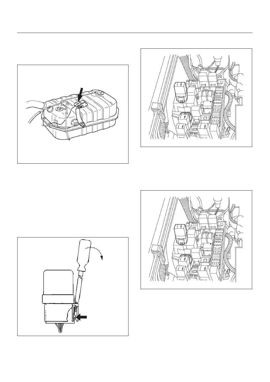
Fuel Pump Relay
Removal Procedure
1. Remove the fuse and relay box cover from under the
hood.
2. Consult the diagram on the cover to determine which
is the correct relay.
3. Insert a small screwdriver into the catch slot on the
forward side of the fuel pump relay.
D
The screwdriver blade will release the catch inside.
D08RY00291
4. Pull the relay straight up and out of the fuse and relay
box.
060R200195
Installation Procedure
1. Insert the relay into the correct place in the fuse and
relay box with the catch slot facing forward.
2. Press down until the catch engages.
D
An audible “click” will be heard.
060R200195
3. Install the fuse and relay box cover.