Isuzu Amigo / Axiom / Trooper / Rodeo / VehiCross. Manual - part 778
6E–136
TROOPER 6VE1 3.5L ENGINE DRIVEABILITY AND EMISSIONS
Diagnostic Trouble Code (DTC) P0106 MAP System Performance
D06R200048
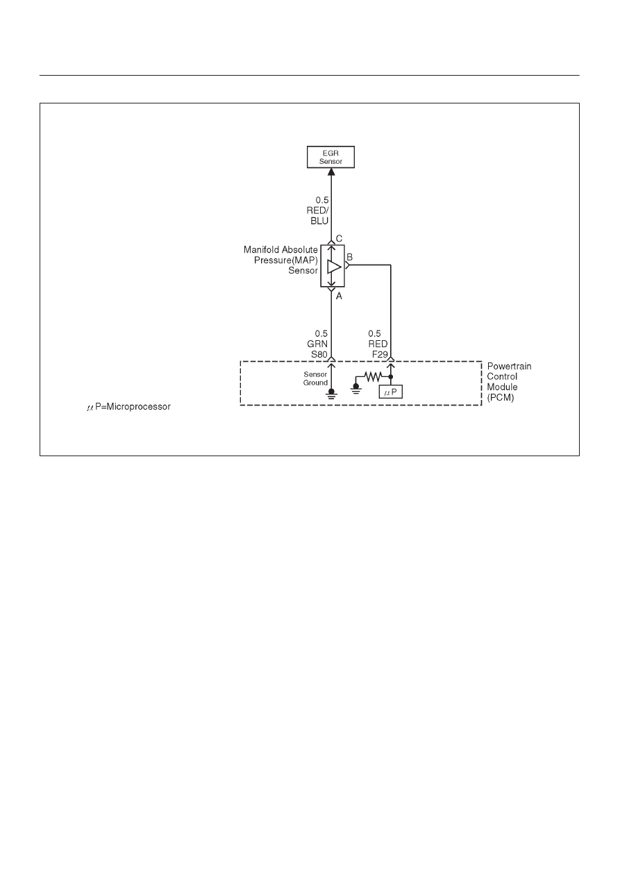
Circuit Description
The manifold absolute pressure (MAP) sensor responds
to changes in intake manifold pressure (vacuum). The
MAP sensor signal voltage to the powertrain control
module (PCM) varies from below 2 volts at idle (high
vacuum) to above 4 volts at wide-open throttle (low
vacuum) at sea level.
The MAP sensor is used to determine manifold pressure
changes while the linear exhaust gas recirculation (EGR)
flow test diagnostic is being run (refer to DTC P0401),
engine vacuum level for some other diagnostics, and
barometric pressure (BARO). The PCM compares the
MAP sensor signal to a calculated MAP based on throttle
position and various engine load factors. If the PCM
detects a MAP signal that varies excessively above or
below the calculated value, DTC P0106 will set.
Conditions for Setting the DTC
D
No TP sensor DTCs are present.
D
Engine speed is steady, changing less then 100 RPM.
D
Engine speed is between 1000 rpm and 4000 rpm.
D
Throttle position is steady, throttle angle changes less
than 1%.
D
EGR flow rate is steady, changing less than 4%.
D
No change in brake switch, A/C clutch, TCC or power
steering pressure switch status.
D
Above conditions are met for longer than 1 second.
D
Actual MAP value varies more than 10 kPa.
D
The MAP value must vary for a total of 10 seconds over
a 20-second period of time that the samples were
monitored.
D
The failure must occur for 2 consecutive trips.
Action Taken When the DTC Sets
D
The PCM will illuminate the malfunction indicator lamp
(MIL) after the second consecutive trip in which the
fault is detected.
D
The PCM will default to a BARO value of 79.3 kPa.
D
The PCM will store conditions which were present
when the DTC was set as Freeze Frame and in the
Failure Records data.
Conditions for Clearing the MIL/DTC
D
The PCM will turn the MIL “OFF” on the third
consecutive trip cycle during which the diagnostic has
been run and the fault condition is no longer present.
D
A history DTC P0106 will clear after 40 consecutive
warm-up cycles have occurred without a fault.
D
DTC P0106 can be cleared by using the Tech 2 “Clear
Info” function or by disconnecting the PCM battery
feed.
Diagnostic Aids
Check for the following conditions:
D
Poor connection at PCM – Inspect harness connectors
for backed-out terminals, improper mating, broken
locks, improperly formed or damaged terminals, and
poor terminal-to-wire connection.