Isuzu Amigo / Axiom / Trooper / Rodeo / VehiCross. Manual - part 776
6E–128
TROOPER 6VE1 3.5L ENGINE DRIVEABILITY AND EMISSIONS
Diagnostic Trouble Code (DTC) P0101 MAF System Performance
D06R200047
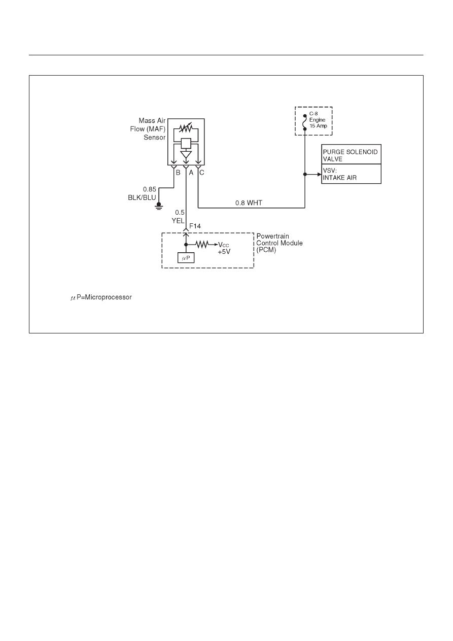
Circuit Description
The mass air flow (MAF) sensor measures the amount of
air which passes through it into the engine during a given
time. The powertrain control module (PCM) uses the
mass air flow information to monitor engine operating
conditions for fuel delivery calculations. A large quantity
of air entering the engine indicates an acceleration or high
load situation, while a small quantity or air indicates
deceleration or idle.
The MAF sensor produces a frequency signal which can
be monitored using a Tech 2. The frequency will vary
within a range of around 3 to 7g/s at idle. DTC P0101 will
be set if the signal from the MAF sensor does not match a
predicted value based on throttle position and engine
RPM.
Conditions for setting the DTC
D
The engine is running.
D
No TP sensor and MAP sensor DTCs are set.
D
No MAF frequency DTCs are set.
D
System voltage is between 11.5 volts and 16 volts.
Action Taken When the DTC Sets
D
The PCM will ON the MIL after second trip with
detected fault.
D
The PCM calculates an air flow value based on idle air
control valve position, throttle position, RPM and
barometric pressure.
D
The PCM will store condition which were present when
the DTC was set as Freeze Frame and in the Failure
Records data.
Conditions for Clearing the MIL/DTC
D
The PCM will turn the MIL “OFF” on the third
consecutive trip cycle during which the diagnostic has
been run and the fault condition is no longer present.
D
A history DTC P0101 will clear after 40 consecutive trip
cycles during which the warm up cycles have occurred
without a fault.
D
DTC P0101 can be cleared using the Tech 2 “Clear
Info” function or by disconnecting the PCM battery
feed.
Diagnostic Aids
An intermittent may be caused by the following:
D
Poor connections.
D
Misrouted harness.
D
Rubbed through wire insulation.
D
Broken wire inside the insulation.
D
The duct work at the MAF sensor for leaks.
D
An engine vacuum leak.
D
The PCV system for vacuum leaks.
D
An incorrect PCV valve.
D
The engine oil dip stick not fully seated.
D
The engine oil fill cap loose or missing.
Check for the following conditions:
D
Poor connection at PCM-Inspect harness connectors
for backed out terminals, improper mating, broken