Isuzu Amigo / Axiom / Trooper / Rodeo / VehiCross. Manual - part 750
6E–24
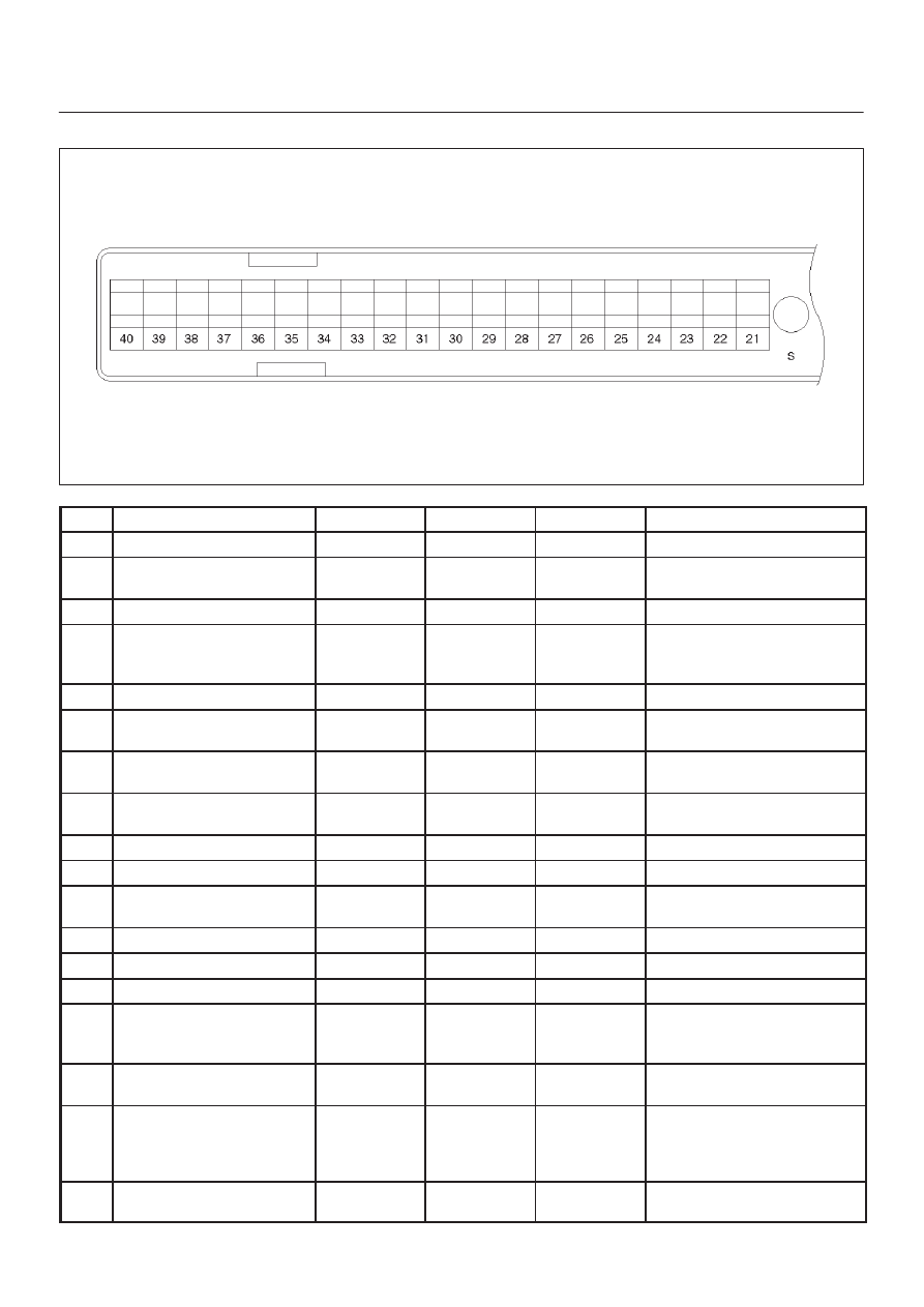
TROOPER 6VE1 3.5L ENGINE DRIVEABILITY AND EMISSIONS
PCM Pinout Table, 80-Way Red Connector – Row “S21
∼
40”
060RY00049
PIN
PIN Function
Wire Color
IGN ON
ENG RUN
Refer To
S21
Not Used
—
—
—
—
S22
Transmissin Output Speed
Sensor
RED
0.0V
0.0V
4L30E T/Mission
S23
PCM Ground
BLK/RED
0.0V
0.0V
Chassis Electrical
S24
Bank 1 HO2S 2 Ground
Jump
RED
0.0V
0.0V
General Description and
Operation, Catalyst Monitor
HO2S 2
S25
Not Used
—
—
—
—
S26
EGR Control Low
BLK/YEL
B+
B+
General Description and
Operation, EGR Control
S27
VSS Input
Light
GRN/WHT
0.0V
0.1V (at rest)
Chassis Electrical
S28
Injector Cylinder #6
GRN/YEL
B+
B+
General Description and
Operation, Fuel Injector
S29
Winter Switch
VIO/GRN
B+
B+
4L30E T/Mission
S30
Auto Cruise Main Switch
PNK/BLK
0.0V
0.0V
Chassis Electrical
S31
Transmissin Range
Signal“2–3’’
GRN
0.0V
0.0V
4L30E T/Mission
S32
Ignition Feed
RED/BLU
B+
B+
Chassis Electrical
S33
TCC Solenoid
RED/BRN
0.0V
0.0V
T/Mission
S34
Not Used
—
—
—
—
S35
ION Sensing Module
RED/GRN
1.555V
1.555V
General Description and
Operation, ION Sensing
Module
S36
5Volt Referrence (AP
Sensor 1)
BLK
5.0V
5.0V
AP Sensor
S37
5Volt Referrence (Fuel
Tank Pressure
Sensor/MAP Sensor/EGR
Posistion Sensor)
RED/BLU
5.0V
5.0V
(Fuel Tank Pressure
Sensor/MAP Sensor/EGR
Posistion Sensor) Sensor
S38
5Volt Referrence (TP
Sensor 1)
RED/BLU
5.0V
5.0V
TP Sensor