Isuzu Amigo / Axiom / Trooper / Rodeo / VehiCross. Manual - part 655
4C–46
DRIVE SHAFT SYSTEM
Disassembly
401RW057
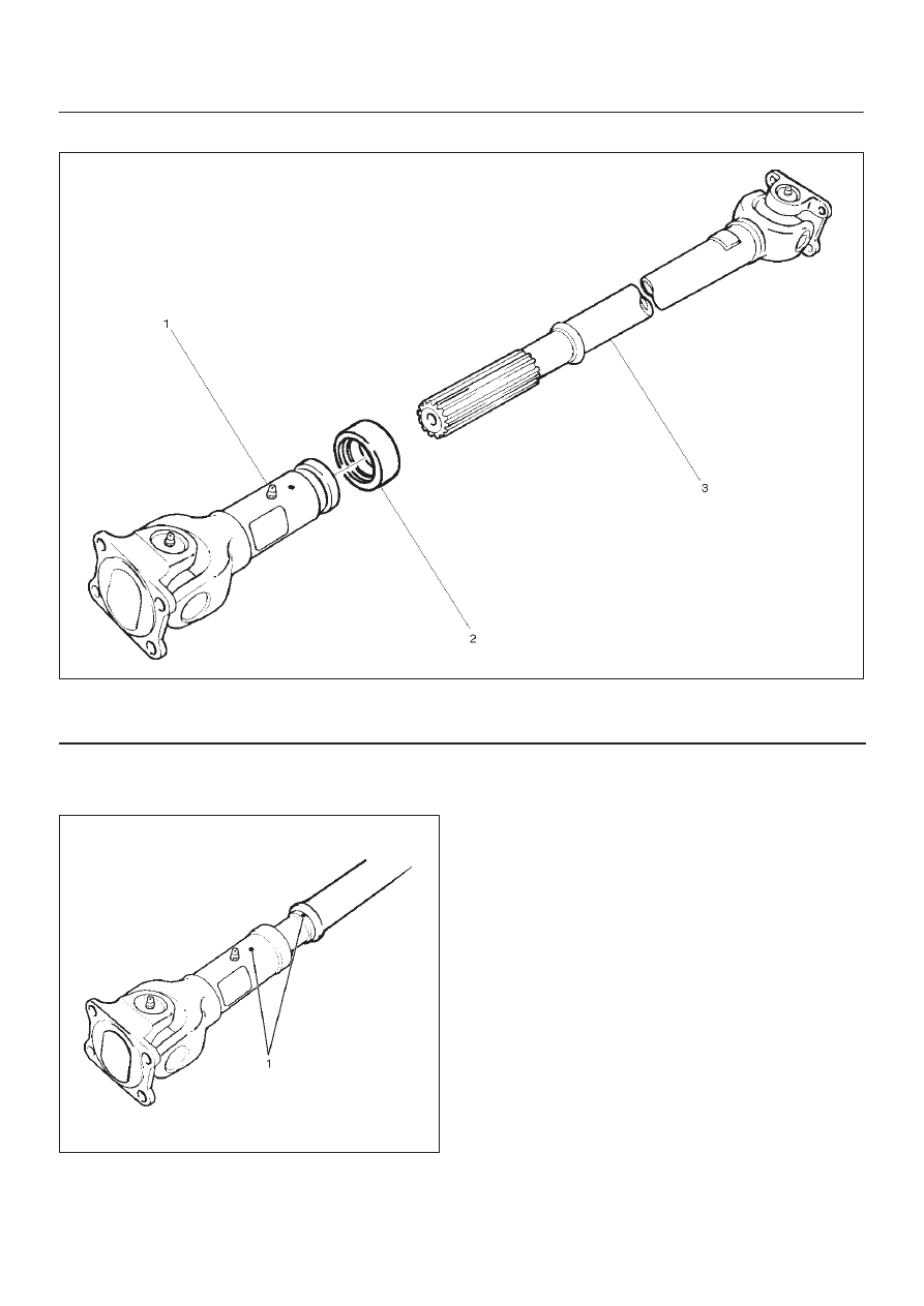
Legend
(1) Sleeve Yoke
(2) Seal
(3) Tube Assembly
1. Apply alignment marks (1) on the sleeve yoke and
tube assembly then remove sleeve yoke.
401RW056
2. Remove seal.
3. Remove tube assembly.