Isuzu Amigo / Axiom / Trooper / Rodeo / VehiCross. Manual - part 651


  Index      Isuzu     Isuzu Amigo / Axiom / Trooper / Rodeo / VehiCross - service repair manual 1999-2002 year


Search            


Content   ..  649  650  651  652   ..


Isuzu Amigo / Axiom / Trooper / Rodeo / VehiCross. Manual - part 651


4C–30

DRIVE SHAFT SYSTEM

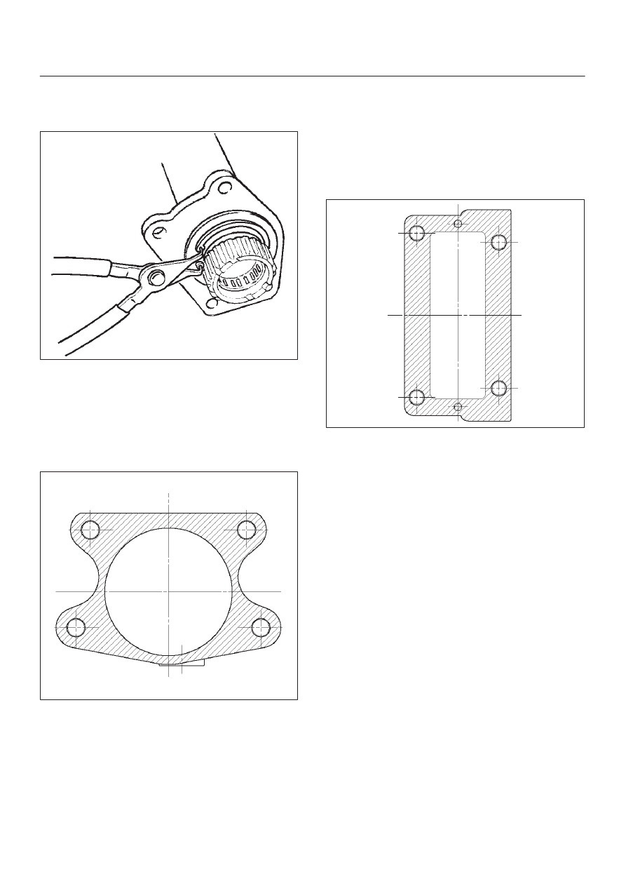
6. Install snap ring (internal) in the groove of front axle

case.

NOTE: Be sure to install the snap ring properly.

412RW017

7. Apply differential gear oil to clutch gear, then install

clutch gear.

8. Apply differential gear oil to sleeve, then install

sleeve.

9. Clean contact surface with the front axle and actuator

mounting surface. Apply liquid gasket  to the contact
surface on the front axle case, then install in the
housing.

412RW023

10. Tighten bolts to specified torque.

Torque: 116N·m(85 lb ft)

11. Clean the actuator contact surface with the housing

then Install and tighten shift position switch to
specified torque.

Torque: 39N·m (29 lb ft)

12. Apply liquid gasket to the contact surface on the

actuator side.

412RW012

13. Align shift arm with the groove of sleeve and install the

actuator.

14. Tighten bolts to specified torque.

Torque: 13N·m(113 lb ft)

15. Install front axle drive shaft and mounting bracket.

Tighten fitting bolts to specified  torque.

Torque: 116N·m (85 lb ft)

16. Pour specified amount of differential gear oil to filler

plug.

Front Differential

Oil Capacity: 1.4lit (1.48US qt)

Actuator Housing

Oil Capacity: 0.12lit(0.13US qt)

17. Install filler plug through gasket and tighten to

specified torque.

Torque: 7.8N·m (58lb ft)

4C–31

DRIVE SHAFT SYSTEM

Main Data and Specifications

General Specifications

Front drive axle oil capacity

1.4 liter (1.48 US qt)(Differential)

0.12 liter (0.13 US qt)(Actuator Housing:Shift on the fly)

Type of lubricant

GL–5 (Multi grade type) Refer to chart in General Information

Axle shaft type

Constant velocity joint(Birfield joint type and double offset joint)

Torque Specifications

E04RW004

4C–32

DRIVE SHAFT SYSTEM

Special Tools

ILLUSTRATION

TOOL NO.

TOOL NAME

J–39378

Remover and Installer;

Front Axle mount

bushing

J–37452

Remover and Installer;

Inner shaft bearing

J– 26941

Remover;Bearing needle

J–2619–01

Hammer; Sliding

J–41693

Installer; Oil seal

J–41694

Installer; Bearing needle

ILLUSTRATION

TOOL NO.

TOOL NAME

J–8092

Grip

4C–33

DRIVE SHAFT SYSTEM

Front Propeller Shaft

General Description

Since the propeller shaft is balanced carefully, welding or
any other modifications are not permitted.

Alignment marks should be applied to each propeller
shaft before removal.

401RW002


Content   ..  649  650  651  652   ..