Isuzu Amigo / Axiom / Trooper / Rodeo / VehiCross. Manual - part 620


  Index      Isuzu     Isuzu Amigo / Axiom / Trooper / Rodeo / VehiCross - service repair manual 1999-2002 year


Search            


Content   ..  618  619  620  621   ..


Isuzu Amigo / Axiom / Trooper / Rodeo / VehiCross. Manual - part 620


4B1–24

DRIVE LINE CONTROL SYSTEM (SHIFT ON THE FLY)

Removal

1. Remove lower cluster assembly and front console

assembly.
Refer to Interior Trim in Body and Accessories
section.

2. Remove nut.
3. Remove 4WD control unit.
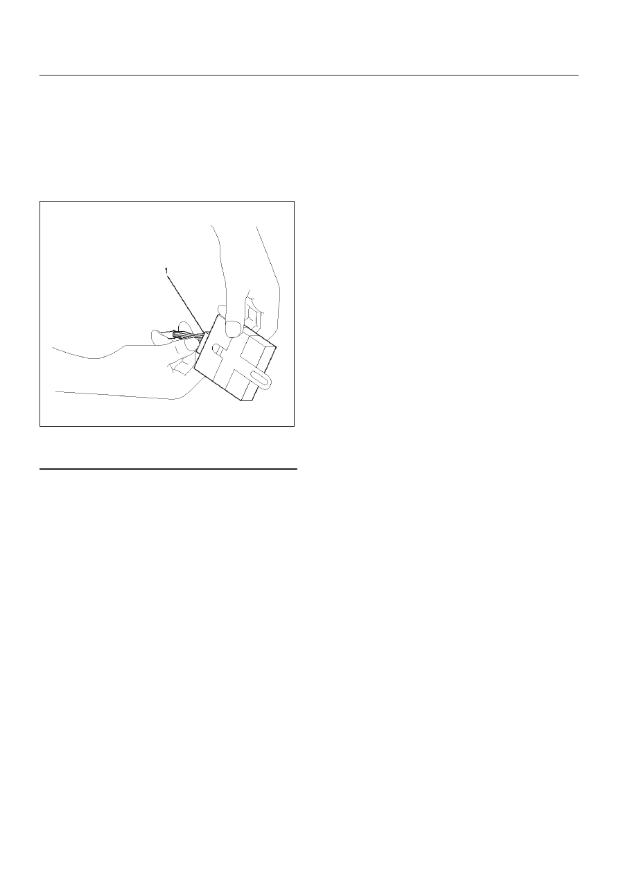
4. Disconnect harness connector (1).

412RW045

Legend

(1) Harness Connector

Installation

1. Connect harness connector, then install 4WD control

unit.

2. Install lower cluster assembly and front console

assembly.

4B2–1

DRIVE LINE CONTROL SYSTEM (TOD)

TROOPER

DRIVELINE/AXLE

DRIVELINE CONTROL SYSTEM (TOD)

CONTENTS

Service Precaution

4B2–1

. . . . . . . . . . . . . . . . . . . . . . 

General Description

4B2–2

. . . . . . . . . . . . . . . . . . . . . 

System Components

4B2–4

. . . . . . . . . . . . . . . . . . . . 

Parts Location

4B2–4

. . . . . . . . . . . . . . . . . . . . . . . . 

Functions of Indicator Lamp

4B2–8

. . . . . . . . . . . . . . 

Diagnosis

4B2–12

. . . . . . . . . . . . . . . . . . . . . . . . . . . . . . 

Basic Diagnostic Flow Chart

4B2–16

. . . . . . . . . . . . . . 

Parts Location

4B2–17

. . . . . . . . . . . . . . . . . . . . . . . . . . 

Circuit Diagram

4B2–18

. . . . . . . . . . . . . . . . . . . . . . . . . 

Connector List

4B2–21

. . . . . . . . . . . . . . . . . . . . . . . . . . 

Checking Failed Pin

4B2–23

. . . . . . . . . . . . . . . . . . . . . 

Checking Failed TOD Control Unit Pin

4B2–26

. . . . . 

Diagnostic Trouble Codes

4B2–31

. . . . . . . . . . . . . . . . 

Diagnosis from Trouble Codes

4B2–32

. . . . . . . . . . . . 

Trouble Diagnosis Depending on The Status
 of TOD Indicator

4B2–56

. . . . . . . . . . . . . . . . . . . . . . . . 

Diagnosis from Symptom

4B2–85

. . . . . . . . . . . . . . . . . 

Service Precaution

WARNING: THIS VEHICLE HAS A SUPPLEMENTAL
RESTRAINT SYSTEM (SRS). REFER TO THE SRS
COMPONENT AND WIRING LOCATION VIEW IN
ORDER TO DETERMINE WHETHER YOU ARE
PERFORMING SERVICE ON OR NEAR THE SRS
COMPONENTS OR THE SRS WIRING. WHEN YOU
ARE PERFORMING SERVICE ON OR NEAR THE SRS
COMPONENTS OR THE SRS WIRING, REFER TO
THE SRS SERVICE INFORMATION. FAILURE TO
FOLLOW WARNINGS COULD RESULT IN POSSIBLE
AIR BAG DEPLOYMENT, PERSONAL INJURY, OR
OTHERWISE UNNEEDED SRS SYSTEM REPAIRS.

CAUTION: Always use the correct fastener in the
proper location. When you replace a fastener, use
ONLY the exact part number for that application.
ISUZU will call out those fasteners that require a
replacement after removal. ISUZU will also call out
the fasteners that require thread lockers or thread
sealant. UNLESS OTHERWISE SPECIFIED, do not
use supplemental coatings (Paints, greases, or other
corrosion inhibitors) on threaded fasteners or
fastener joint interfaces. Generally, such coatings
adversely affect the fastener torque and the joint
clamping force, and may damage the fastener. When
you install fasteners, use the correct tightening
sequence and specifications. Following these
instructions can help you avoid damage to parts and
systems.

SECTION

DRIVE LINE CONTROL SYSTEM (TOD)

4B2–2

General Description

C07RY00003

TOD (Torque on Demand) system is traction state control
system to vehicle.

Transfer Position and Drive Mode

Three drive modes can be selected through operation of
4WD switch and transfer lever.

Transfer Position

4WD AUTO

SWITCH

Mode

Drive mode

HIGH

ON

2H

Rear wheel drive

OFF

TOD

Electronically controlled torque split
four wheel drive

4L

ON/OFF

4L

Low-speed mechanical lock-up four
wheel drive

The electronic control unit (ECU) judges the signals from
the transfer lever and controls the transfer drive mode
and shift-on-the-fly system status.

TOD Control

The TOD position usually drives the rear wheels, and
transmits the torque to the front wheels with the help of
electronically controlled torque split mechanism
according to running conditions encountered.  The driving
force is directly transmitted to the rear wheels.  This force
is split by the transfer and delivered to the front wheels.
The magnitude of the torque transmitted to the front
wheels is controlled by changing the pressing force of the
multi plate disk clutch built in the transfer unit.  The

pressing force of the clutch is controlled by changing the
voltage to the electromagnetic coil mounted to the rear of
the clutch.  When the clutch is completely disengaged,
the rear wheels are driven.  When the clutch is completely
engaged, a rigid four wheel drive mode is obtained.  The
torque split status is controlled continuously between the
rear wheel and four wheel drive modes.  This system
includes front and rear speed sensors, and receives
throttle position sensor information from the PCM.
The control unit receives signals sent from these sensors
and changes the pressing force of the multi plate disk
clutch to determine the torque distribution on the front and
rear wheels.  Therefore, when the slip of the rear wheels is
increased against the current torque level in the normal

4B2–3

DRIVE LINE CONTROL SYSTEM (TOD)

rear wheel drive mode, the control unit detects the slip
condition, determines the optimum torque based on the
feedback control logic, and increases the torque to the
front wheels.
The control unit uses the signal from the throttle position
sensor to predict the future vehicle condition and the
intention of the driver with respect to acceleration and
deceleration, and determines the initial torque distribution
using these data and the information from the speed
sensors.
In case of small circle turning in the parking lot, for
example, the control unit minimizes the clutch pressing
force to restrict a braking phenomenon.  When the ABS
becomes active, the control unit optimizes the clutch
pressing force to ensure stable braking.

TOD Indicator Control

The TOD indicator on the instrument panel informs the
driver of the current working status of the transfer unit.
The information consists of two items: the drive mode
(2H, TOD, 4L, transition) and the torque split status of the
TOD (torque distribution level).  The indicator can display
occasional errors and corresponding error codes.


Content   ..  618  619  620  621   ..