Isuzu Amigo / Axiom / Trooper / Rodeo / VehiCross. Manual - part 619


  Index      Isuzu     Isuzu Amigo / Axiom / Trooper / Rodeo / VehiCross - service repair manual 1999-2002 year


Search            


Content   ..  617  618  619  620   ..


Isuzu Amigo / Axiom / Trooper / Rodeo / VehiCross. Manual - part 619


4B1–20

DRIVE LINE CONTROL SYSTEM (SHIFT ON THE FLY)

Inspection And Repair
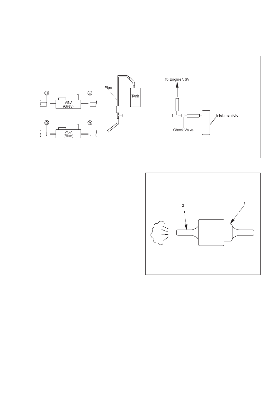
Vacuum Piping

C04RW008

1. Pull out the Hose A in figure and install a vacuum

gauge.

2. Plug up Hose B in figure to prevent the leak of

vacuum.

3. Start the engine and measure vacuum 2 or 3 minutes

afterward.

4. Repeat 1) and 2) but with Hose A plugged and Hose B

pulled out.

5. If vacuum measures –400mmHg, or if it shows a

sudden drop immediately after engine stop, inspect
the hose, tank, and pipe for damage.

NOTE: Be careful not to permit the entry of dust and
water during inspection.

6. Pull out Hose D in above illustration.
7. Plug Hose E in above illustration.
8. Make sure that Hose D in above illustration is under

atmospheric pressure.

9. Pull out Hose E and plug Hose D, and make sure that

Hose E is under atmospheric pressure.

10. If Check 8) or 9) has revealed stoppage, check and

see that there is no bend, foreign matter in the hose or
in the filter. If there is trouble, repair or replace.

Check Valve

C04RS004

1. Apply vacuum from the orange colored side(1).

Vacuum:–400mmHg

2. Check leakage of vacuum.
3. Make sure that vacuum cannot be applied from the

black colored side(2).

4. If vacuum is not applicable as much as –400mmHg,

and if there is resistance on the intake side, replace
with a new check valve.

4B1–21

DRIVE LINE CONTROL SYSTEM (SHIFT ON THE FLY)

VSV Assembly

Inspect the vehicle side harness as follows:

412RS071

Legend

(1) Grey
(2) Blue

1. Remove connector.
2. Shift transfer lever to 2H and start the engine.

NOTE: Do not move the vehicle while inspection.

3. Make sure that there is continuity in the vehicle side of

harness. If there is no continuity, check transfer shift
switch and wiring.

Inspect both VSVs as follows:

F04RS004

1. With battery not connected (Usual).

A–C:There is continuity

B:Closed

2. With battery connected

A – B:There is continuity

C:Closed

3. If 1) and 2) fail, replace with a new VSV.

Axle Position Switch

412RS048

1. With ball (1) being free

A – B:There is continuity

2. With ball forced into the switch

A – B:No continuity

3. If 1) and 2) fail, replace with a new switch.

Motor Actuator Assembly

Inspect the function of the motor actuator assembly as
follows:

4B1–22

DRIVE LINE CONTROL SYSTEM (SHIFT ON THE FLY)

1. Disassemble the motor actuator from transfer rear

case.

412RW037

Legend

(3) Shift Rod
(4) Connector

2. Connect the terminals as shown in figure.

Shift rod of the motor actuator moves and stops
at 4WD position.

412RX001

Legend

(1) 2WD
(2) 4WD
(3) Shift Rod
(4) Connector

3. Connect the terminals as shown in figure.

Shift rod of the motor actuator moves and stops
at 2WD position.

412RX002

Legend

(1) 2WD
(2) 4WD
(3) Shift Rod
(4) Connector

4. If 2) and 3) fail, replace with a new motor actuator.

Transfer Position Switch

412RW040

Legend

(1) Ball

1. With ball being free.

A–B : There is continuity.

2. With ball forced into the switch.

A–B : No continuity.

3. If 1) and 2) fail, replace with a new switch.

4B1–23

DRIVE LINE CONTROL SYSTEM (SHIFT ON THE FLY)

4WD Control Unit

4WD Control Unit Associated Parts

412RW044

Legend

(1) Lower Cluster Assembly
(2) Front Console Assembly

(3) Harness Connector
(4) Nut
(5) 4WD Control Unit


Content   ..  617  618  619  620   ..