Isuzu Amigo / Axiom / Trooper / Rodeo / VehiCross. Manual - part 600


  Index      Isuzu     Isuzu Amigo / Axiom / Trooper / Rodeo / VehiCross - service repair manual 1999-2002 year


Search            


Content   ..  598  599  600  601   ..


Isuzu Amigo / Axiom / Trooper / Rodeo / VehiCross. Manual - part 600


DIFFERENTIAL (FRONT)

4A1–10

Disassembly

1. Remove differential carrier fixing bolt.
2. Remove differential assembly.
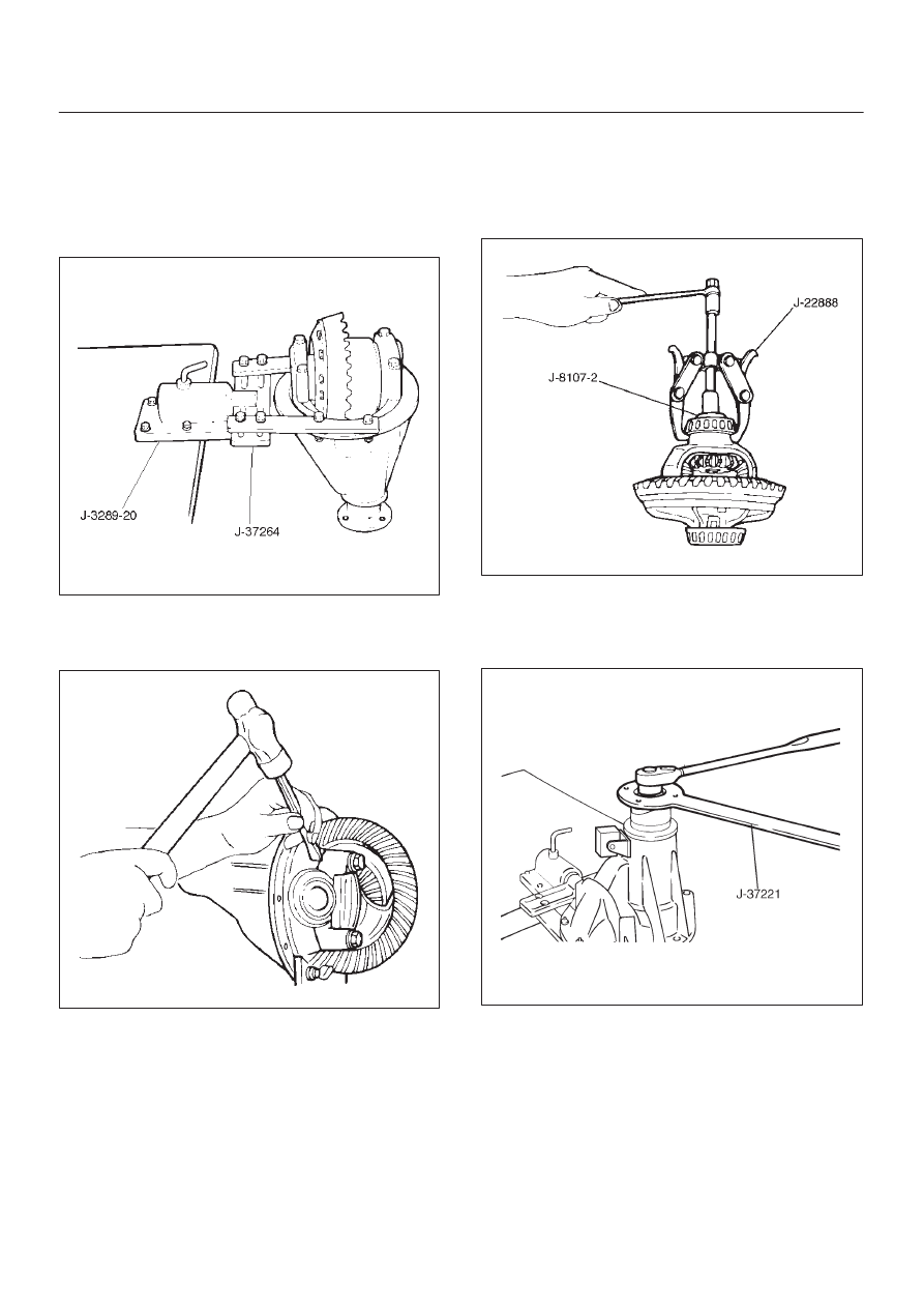
3. Using holding fixture J–37264 and holding fixture

base J–3289–20, fix the differential assembly to the
bench.

425RS008

4. Remove bearing cap bolt.
5. Apply a setting mark to the side bearing cap and the

differential carrier then remove bearing cap.

425RS009

6. Remove differential cage assembly.

7. Remove side bearing outer race, after removal, keep

the right and left hand side bearing assemblies
separate to maintain inner and outer race
combinations.

8. Remove side bearing, using remover J–22888 and

adapter J–8107–2.

415RS005

9. Remove adjust shim, note the thickness and position

of the shims removed.

10. Remove the flange nut using holding wrench J–37221

after raising up its staked parts completely.

425RW040

11. Remove flange.

12. Remove dust cover.

4A1–11

DIFFERENTIAL (FRONT)

13. Remove the drive pinion assembly using a soft metal

rod and a hammer.

425RW041

14. Remove collapsible spacer.
15. Remove the inner bearing using a separator

J–22912–01 and a press.

415RS006

16. Remove adjust shim.
17. Remove inner bearing outer race.
18. Remove oil seal.
19. Remove outer bearing.

20. Remove the inner bearing outer race (1) and the outer

bearing outer race (2) by using a brass bar and a
hammer.

425RS014

425RS015

DIFFERENTIAL (FRONT)

4A1–12

21. Remove damper and bracket.

425RW042

Reassembly

1. Using installer J–24256 and grip J–8092, install outer

bearing outer race.

415RS007

2. Using installer J–24252 and grip J–8092, install Inner

bearing outer race.

415RS008

3. Install adjust shim and adjust drive pinion mounting

distance
1. Apply gear oil to the inner and outer drive pinion

bearing.
Clean the pinion setting gauge set.
Then install the gauge set together with the inner
and outer bearings.

2. Tighten the nut to the specified torque.

Torque: 2.3 N·m (20 lb in)

415RS009

Legend

(1) Pilot : J–21777–42
(2) Nut and Bolt : J–23597–9
(3) Gauge Plate : J–23597–7

4A1–13

DIFFERENTIAL (FRONT)

3. Clean the side bearing bores. Install the dial

indicator with the discs and arbor. Install and
tighten the bearing caps to the specified torque.

Torque: 98 N·m (72 lb ft)

415RS010

Legend

(1) Dial Indicator: J–8001
(2) Disc (2 pcs.): J–23597–8
(3) Arbor: J–23597–1
(4) Gauge Plate: J–23597–42

4. Set the dial indicator to “0”. Place it on the

mounting post of the gauging arbor with the
contact button touching the indicator pad. Force
the dial indicator downward until the needle has
made a half turn clockwise. Tighten down the dial
indicator in this position.

425RS020

Legend

(1) Dial Indicator
(2) Ganging Arbor
(3) Plunger
(4) Gauge Plate

5. Position the plunger on the gauge plate. Move the

gauging arbor slowly back and forth and locate
the position at which the dial indicator shows the
greatest defection. At this point, once again set
the dial indicator to “0”.
Repeat the procedure to verify the “0” setting.

425RS021

6. After the ZERO setting is obtained, rotate the

gauging arbor until the dial indicator rod does not
touch the gauging plate.
Record the number the dial indicator needle
points to.

425RS022

Legend

(1) Example=Dial indicator reading of 0.085


Content   ..  598  599  600  601   ..