Isuzu Amigo / Axiom / Trooper / Rodeo / VehiCross. Manual - part 566


  Index      Isuzu     Isuzu Amigo / Axiom / Trooper / Rodeo / VehiCross - service repair manual 1999-2002 year


Search            


Content   ..  564  565  566  567   ..


Isuzu Amigo / Axiom / Trooper / Rodeo / VehiCross. Manual - part 566


1A–132 HEATING, VENTILATION AND AIR CONDITIONING (HVAC)

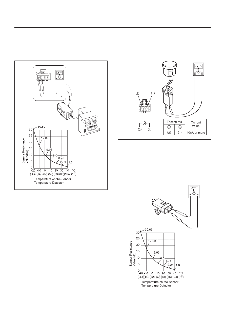
Individual Inspection

In Car Sensor

1. Disconnect the in car sensor connector (I–34).
2. Measure resistance between the in car sensor side

terminal No.I34–3 and No.I34–4.

C01R200018

Sun Sensor

1. Disconnect the sun sensor connector (I–35).
2. Measure the current value on the sun sensor when

placed it approximately 15 cm away from 60W
incandescent lamp.

D06R200101

Ambient Sensor

1. Disconnect the connector (C–86) on the ambient

sensor.

2. Measure resistance between the ambient sensor side

terminals. 

C01R200014

HEATING, VENTILATION AND AIR CONDITIONING (HVAC) 1A–133

Power Transistor 

1. Remove the power transistor connector (I–50) from

the evaporator assembly. 

2. Check the conduction between the power transistor

side terminals.

C01R200017

In Car Sensor

1. Turn on the ignition switch (the engine is started).

Start the air conditioner in “Full Auto”.

2. Make sure that the in car sensor suctions cigarette

smokes and such.

In Car Sensor

1. Dismount the in car sensor from the automatic

heater/air conditioner control unit.  Connect (+) end
and (–) end of the battery to the aspirator motor side
terminals No.I34–1 and No.I34–2, respectively, then
check if the motor runs normally.

C01RY00005

1A–134 HEATING, VENTILATION AND AIR CONDITIONING (HVAC)

Heater (B–36), Thermostat (X–5), And
Compressor (X–7) Relay

1. Disconnect relays and check for continuity and

resistance between relay terminals.

D

For handling of these relays, refer to Heater Relay
in this section.

901RY00041

Triple Pressure Switch (V6, A/T)

1. Disconnect the connector and check for continuity

between pressure switch side connector terminals (1)
and (2).

2. Reconnect the connector to activate the A/C switch,

and check to see if there is continuity between the
chassis side connector terminal (3) and (4) and the
fan operates.

875R200031

HEATING, VENTILATION AND AIR CONDITIONING (HVAC) 1A–135

On-Vehicle Service

Power Transistor

874RY00010

Legend

(1) Evaporator Assembly
(2) Power Transistor
(3) Power Transistor Connector
(4) Instrument Panel Passenger Lower Cover
(5) Glove Box
(6) Front Console
(7) Lower Cluster
(8) Passenger Knee Bolster Reinforcement

Removal

1. Remove front console.
2. Remove lower cluster.
3. Remove glove box.
4. Remove instrument panel passenger lower cover.
5. Remove passenger knee bolster reinforcement.
6. Disconnect the power transistor connector.
7. Remove power transistor.

Installation

To install, follow the removal step in the reverse order.

Automatic Heater/Air Conditioner
Control Unit

865RY00012

Legend

(1) Connector
(2) Set Screw
(3) Instrument Panel Cluster
(4) Automatic Air Conditioner Control Unit

Removal

1. Disconnect the battery ground cable.
2. Remove instrument panel cluster.

D

Refer to Instrument Panel Assembly in Body
Stractur section.

3. Disconnnect the automatic heater/air conditioner

control unit connector.

4. Remove automatic heater/air conditioner control unit.

Installation

To install, follow the removal step in the reverse order.


Content   ..  564  565  566  567   ..