Isuzu Amigo / Axiom / Trooper / Rodeo / VehiCross. Manual - part 564


  Index      Isuzu     Isuzu Amigo / Axiom / Trooper / Rodeo / VehiCross - service repair manual 1999-2002 year


Search            


Content   ..  562  563  564  565   ..


Isuzu Amigo / Axiom / Trooper / Rodeo / VehiCross. Manual - part 564


1A–124 HEATING, VENTILATION AND AIR CONDITIONING (HVAC)

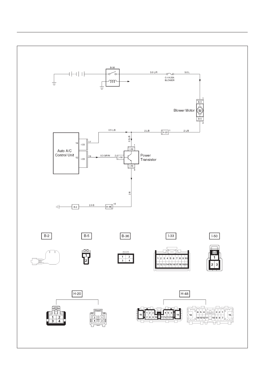
Inspection of the Fan Motor System

D08R200270

HEATING, VENTILATION AND AIR CONDITIONING (HVAC) 1A–125

Condition

Possible cause

Correction

The fan dose not rotate at all

Refer to Chart A

The fan dose not stop

Refer to Chart B

Chart A: Fan Does Not Rotate At All 

Step

Action

Value(s)

Yes

No

1

Are the fuse No.C–19 normal?

Go to Step 2

Replace the

fuse

2

Are the relay No.B–36 normal?

Go to Step 3

Replace the

relay

3

Turn on the ignition switch (the engine is run).

Is the battery voltage applied between the harness side
connector terminal No.B5–1 and ground?

Go to Step 5

Go to Step 4

4

Repair an open circuit between terminal No.B5–1 and
No.C–19 fuse.

Is the action complete?

Go to Step 3

5

Is there continuity between the harness side connector
terminal No.B5–2 and ground (No.B–2)?

Go to Step 7

Go to Step 6

6

Repair an open circuit between terminal No.B5–2 and
ground.

Is the action complete?

7

Is the battery voltage applied between the harness side
connector terminal No.B5–2 and No.B5–1?

Go to Step 8

Go to Step 9

8

Replace the blower motor.

Is the action complete?

Verify repair

9

Refer to chart B and C.

Is the action complete?

Verify repair

Chart B: Fan Does Not Stop 

Step

Action

Value(s)

Yes

No

1

1. Disconnect the power transistor connector I–50 and

the auto A/C control unit connector I–33.

2. Turn on the ignition switch.

Does the blower motor stop?

Go to Step 3

Go to Step 2

2

Repair a short circuit between connector, No.B5–2 and
No.I50–1, or No.B5–2 and I33–17.

Is the action complete?

Verify repair

3

Is the power transistor normal? (Refer to the later
section on “individual inspection”.)

Go to Step 4

Replace the

power

transistor

4

Reinstall the power transistor.

Does the blower motor start operating?

Replace the

auto A/C

control unit

1A–126 HEATING, VENTILATION AND AIR CONDITIONING (HVAC)

Inspection of the Magnetic Clutch System

6VE1 Engine

D08R200272

HEATING, VENTILATION AND AIR CONDITIONING (HVAC) 1A–127

Condition

Possible cause

Correction

Magnetic clutch does not work

Refer to Chart A

Chart A: Magnetic Clutch Does Not work 

Step

Action

Value(s)

Yes

No

1

Is the fuse No.C–20 normal?

Go to Step 2

Replace the

fuse

2

Is the relay No.X–7 (compressor relay) No.X–5 (A/C
thermo relay) and No.B–36 (heater relay) normal?

Go to Step 3

Replace the

relay

3

Is the pressure switch normal?

Go to Step 4

Replace the

pressure

switch

4

1. Turn the ignition switch on. (the engine is run.) 
2. Turn the fun switch and the air conditioner switch

on.

Is the battery voltage applied between the harness side
connector terminal No.E3–1 and the ground?

Go to Step 5

Go to Step 6

5

Repair or replace the magnetic clutch.

Is the action complete?

Verify repair

6

Is there continuity between the harness side connector
terminal No.X7–4 and No.E3–1?

Go to Step 8

Go to Step 7

7

Repair an open circuit between terminal No.X7–4 and
No.E3–1.

Is the action complete?

Go to Step 6

8

Is the battery voltage applied between the harness side
connector terminal No.X7–2 and ground, No.X7–1 and
ground?

Go to Step 10

Go to Step 9

9

Repair an open circuit between terminal No.X7–2 and
fuse No.C–20, No.X7–1 and fuse No.C–20.

Is the action complete?

Go to Step 8

10

Is the battery voltage applied between the harness side
connector terminal No.I33–18 and ground?

Go to Step 12

Go to Step 11

11

Repair an open circuit between terminal No.I33–18 and
No.X7–3.

Is the action complete?

Go to Step 10

12

Is the battery voltage applied between the harness side
connector terminal No.C89–2 and ground?

Go to Step 14

Go to Step 13

13

Repair an open circuit between terminal No.C89–2 and
fuse No.C–20.

Is the action complete?

Go to Step 12

14

Is the battery voltage applied between the harness side
connector terminal No.X5–3 and ground, No.X5–2 and
ground?

Go to Step 16

Go to Step 15

15

Repair an open circuit between terminal No.X5–3 and
No.C89–1, No.X5–2 and fuse No.C–20.

Is the action complete?

Go to Step 14

16

Is the battery voltage applied between the harness side
connector terminal No.I32–14 and ground?

Go to Step 18

Go to Step 17


Content   ..  562  563  564  565   ..