Isuzu Amigo / Axiom / Trooper / Rodeo / VehiCross. Manual - part 562


  Index      Isuzu     Isuzu Amigo / Axiom / Trooper / Rodeo / VehiCross - service repair manual 1999-2002 year


Search            


Content   ..  560  561  562  563   ..


Isuzu Amigo / Axiom / Trooper / Rodeo / VehiCross. Manual - part 562


1A–116 HEATING, VENTILATION AND AIR CONDITIONING (HVAC)
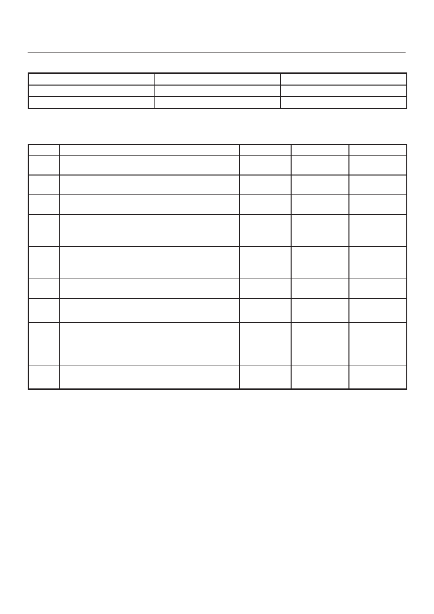
Condition

Possible cause

Correction

Does not work at all

Refer to Chart A

Control failure

Refer to Chart B

Chart A: Does Not Work At All 

Step

Action

Value(s)

Yes

No

1

Is the fuse FL–1 normal?

Go to Step 2

Replace the

fuse

2

Is the fuse C–20 normal?

Go to Step 3

Replace the

fuse

3

Is the relay B–36 normal?

Go to Step 4

Replace the

relay

4

Turn on the ignition switch. (the engine is run.)

Is the battery voltage applied between the harness side
connector terminal No.I49–3 and ground?

Approx 12V

Go to Step 6

Go to Step 5

5

Repair an open circuit between terminal No.I49–3 and
No.B36–4.

Is the action complete?

Go to Step 4

6

Is the battery voltage applied between the harness side
connector terminal No.I49–4 and ground?

Approx 12V

Go to Step 8

Go to Step 7

7

Replace the intake actuator motor.

Is the action complete?

Go to Step 6

8

Is there continuity between the harness side connector
terminal No.I32–11 and No.I49–4?

Go to Step 10

Go to Step 9

9

Repair an open circuit between No.I32–11 and I49–4.

Is the action complete?

Verify repair

10

Replace the auto air conditioner control unit.

Is the action complete?

Verify repair

HEATING, VENTILATION AND AIR CONDITIONING (HVAC) 1A–117

Chart B: Failure on the Intake Control 

Step

Action

Value(s)

Yes

No

1

Is the fuse No.C–20 normal?

Go to Step 2

Replace the

fuse

2

Is the relay No.B–36 normal?

Go to Step 3

Replace the

relay

3

Turn on the ignition switch. (the engine is run.)

Is the intake actuator stopped?

Go to Step 5

Go to Step 4

4

Replace or repair the auto air conditioner control unit.

Is the action complete?

Verify repair

5

Is there continuity between the harness side connector
terminal No.I49–5 and No.I33–11?

Go to Step 7

Go to Step 6

6

Repair an open circuit between terminal No.I49–5 and
No.I33–11.

Is the action complete?

Go to Step 5

7

Is there continuity between the harness side connector
terminal No.I49–6 and No.I33–12?

Go to Step 9

Go to Step 8

8

Repair an open circuit between terminal No.I49–6 and
No.I33–12.

Is the action complete?

Go to Step 7

9

Is there continuity between the harness side connector
terminal No.I49–1 and No.I33–13?

Go to Step 11

Go to Step 10

10

Repair an open circuit between terminal No.I49–1 and
I33-13.

Is the action complete?

Go to Step 9

11

Is there continuity between the harness side connector
terminal No.I49–2 and No.I33–14?

Go to Step 13

Go to Step 12

12

Repair an open circuit between harness No.I49–2 and
No.I33–14.

Is the action complete?

Go to Step 11

13

1. Disconnect the intake actuator connector No.I49.
2. Is the battery voltage applied between harness side

connector terminal
No.I49–6 and ground?
No.I49–2 and ground?
No.I49–1 and ground?

Go to Step 14

Go to Step 15

14

Replace or repair the intake actuator.

Is the action complete?

Verify repair

15

Replace or repair the air conditioner control unit.

Is the action complete?

Verify repair

1A–118 HEATING, VENTILATION AND AIR CONDITIONING (HVAC)

Inspection of the Mix Actuator System

D08R200268

Condition

Possible cause

Correction

Does not work at all

Refer to Chart A

Control failure

Refer to Chart B

HEATING, VENTILATION AND AIR CONDITIONING (HVAC) 1A–119

Chart A: Does Not work At All 

Step

Action

Value(s)

Yes

No

1

1. Turn on the ignition switch (the engine is run).
2. Disconnect the mix actuator connector (I–45).
3. Short-circuit the chassis harness side connector

terminal No.I45–3 and No.I45–7.

4. Using the temperature control lever, select FH for

the temperature.

Is the battery voltage applied on a regular interval basis
between the harness side connector terminal No.I45–6
(-) and No.I45–8 (+)?

Go to Step 3

Go to Step 2

2

Replace the auto air conditioner control unit.

Varify repair

3

Using the temperature control lever, select FC for the
temperature.

Is the battery voltage applied on a regular interval basis
between the harness side connector terminal No.I45–6
(+) and No.I45–8 (-)?

Go to Step 5

Go to Step 4

4

Replace the auto air conditioner control unit.

Verify repair

5

Is there continuity between the harness side connector
terminal No.I32–6 and No.I45–6?

Go to Step 7

Go to Step 6

6

Repair an open circuit between terminal No.I32–6 and
No.I45–6.

Is the action complete?

Go to Step 5

7

Is there continuity between the harness side connector
terminal No.I32–5 and No.I45–8?

Go to Step 9

Go to Step 8

8

Repair an open circuit between terminal No.I32–5 and
No.I45–8.

Is the action complete?

Verify repair

9

Replace the mix actuator.

Is the action complete?

Verify repair


Content   ..  560  561  562  563   ..