Isuzu Amigo / Axiom / Trooper / Rodeo / VehiCross. Manual - part 558
1A–100 HEATING, VENTILATION AND AIR CONDITIONING (HVAC)
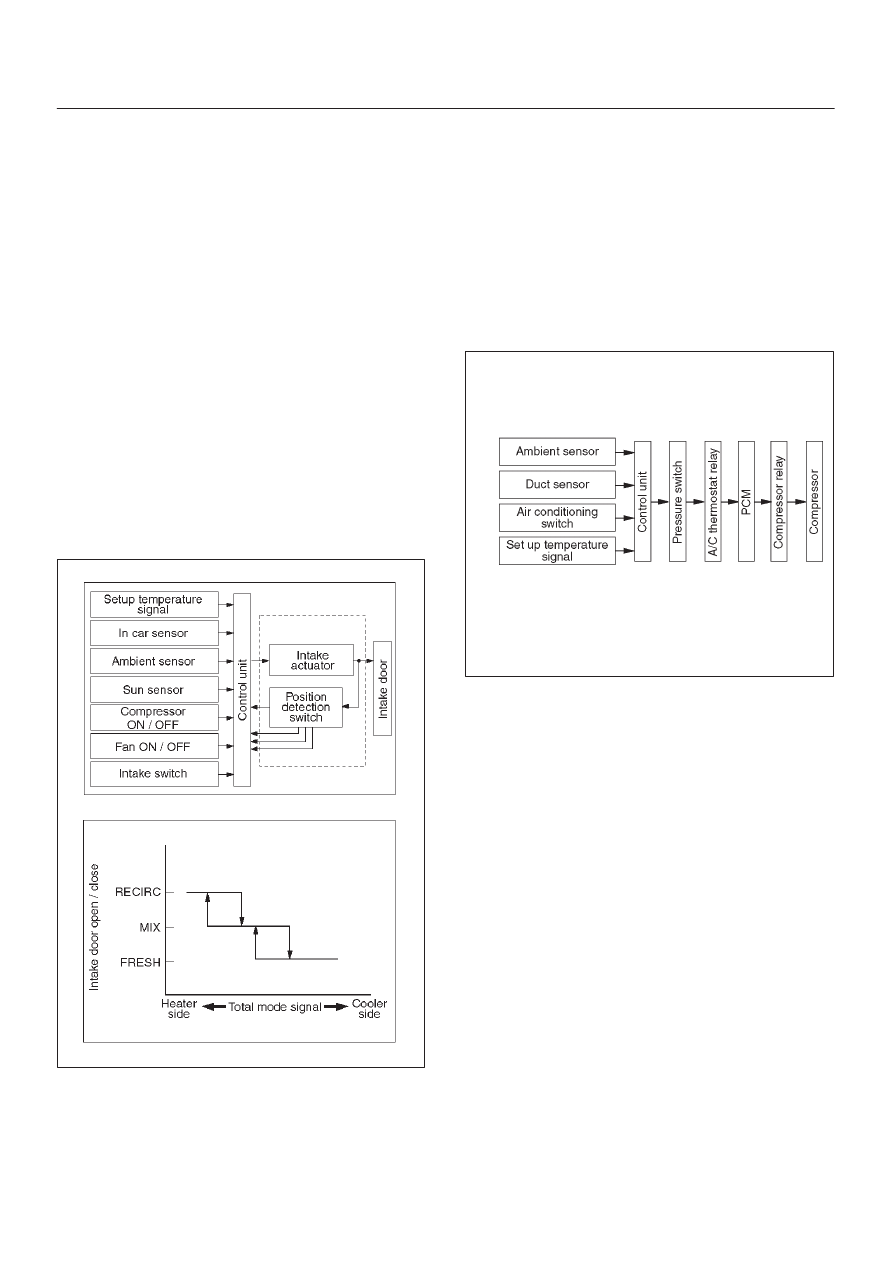
Intake (Fresh air/interior air switching)
Control
In the Full Auto mode, the automatic air conditioner
control unit operates on the setup temperature signal and
other sensor input signals to derive the total signal.
According to the pattern specified by this signal, the
control unit provides the intake control.
When the fan is turned off or the A/C (air conditioning) is
turned off, the intake is fixed to the FRESH mode.
When FC or FH is selected from the control switch, the
intake mode is accordingly fixed to the RECIRC or
FRESH.
In the Manual Operation
D
Pressing the FRESH (fresh air intake) or the RECIRC
(room air circulation) accordingly selects the FRESH
or RECIRC mode.
When the DEF Mode Switch is depressed
D
The intake mode is fixed to the FRESH. When the
MANU REC is selected, however, the mode is fixed
the RECIRC.
When the Mode Switch is depressed
D
If the automatic intake control is selected, the intake is
fixed to the currently selected mode.
C01RY00012
Compressor Control
In the automatic control mode, the automatic air
conditioner control unit turns on or off the compressor
with the evaporator anti–freeze mechanism using the
duct sensor. And, when outside air is detected to be low
through the ambient sensor signal, the control unit turns
off the compressor using the compressor control function.
Manual Control
D
In the automatic control mode, pressing the A/C (air
conditioning) switch turns off the compressor.
D
Pressing the DEF mode switch automatically turns on
the compressor.
C01R200019
Heating Start Timing Control
When the automatic air conditioner is started, heating is
turned on under following conditions.
D
The detected temperature of thermo unit is 58
°
C
(136
°
F) or less.
D
The temperature setting signal and the total signal by
each sensor meet the condition of heating.
When the detected temperature by the coolant
temperature sensor is 58
°
C (136
°
F) or less, the blower
fan motor is set to work at low speed and the “DEF” mode
is selected.
When the detected temperature by the coolant
temperature sensor is 25
°
C (77
°
F) or more, the blow
mode changes automatic control. And the blower fan
speed is controlled to be lineally up from “LO” to “MAX HI”.