Isuzu Amigo / Axiom / Trooper / Rodeo / VehiCross. Manual - part 553


  Index      Isuzu     Isuzu Amigo / Axiom / Trooper / Rodeo / VehiCross - service repair manual 1999-2002 year


Search            


Content   ..  551  552  553  554   ..


Isuzu Amigo / Axiom / Trooper / Rodeo / VehiCross. Manual - part 553


1A–80 HEATING, VENTILATION AND AIR CONDITIONING (HVAC)
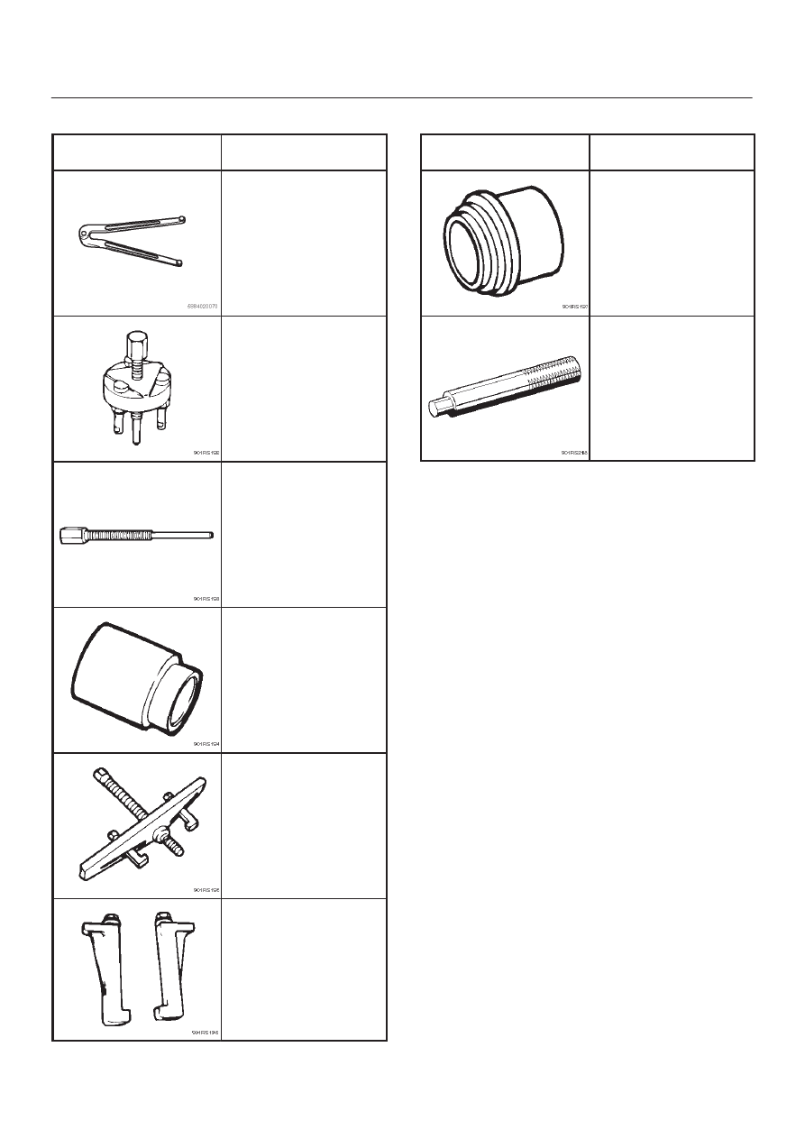
Special Tools

ILLUSTRATION

TOOL NO.

TOOL NAME

J-7624

Drive plate holder

J-33944-A

Drive plate puller

J-33944-4

Forcing screw

J-38424

Pulley puller pilot

J-8433

Pulley puller

J-24092-2

Pulley puller leg

ILLUSTRATION

TOOL NO.

TOOL NAME

J-33940-A

Pulley installer

J-8092

Drive handle

HEATING, VENTILATION AND AIR CONDITIONING (HVAC) 1A–81

Automatic Air Conditioning System

General Description

Using a variety of sensors, this automatic heater and air
conditioner accurately senses outside air temperature,
solar radiation quantity, evaporator’s blowing
temperature, and interior temperature, then enters these
data to the automatic heater/air conditioner control unit
(equipped with the built-in micro-computer).  The data
provided to the control unit enables to automatically
control blow temperature and blow air quantity, turn on or

off the compressor and switch the blow port as well as
switching between the fresh air intake and interior air
circulation.
Resetting the automatic function allows you to switch to
the manual control mode.
The self-diagnoisis function of the automatic heater and
air conditioner control unit (with the built–in
micro–computer) allows the unit to access and diagnose
a failed part easier and quicker.

Full Automatic Air Conditioner Parts Configuration

865R200051

Legend

(1) Sun Sensor
(2) Lower Center Vent Box
(3) Evaporator Assembly
(4) Duct Sensor
(5) Intake Actuator

(6) Blower Unit
(7) Automatic Air Conditioner Control Unit
(8) In Car Sensor
(9) Heater Unit

(10) Mode Actuator

(11) Mix Actuator

1A–82 HEATING, VENTILATION AND AIR CONDITIONING (HVAC)

Refrigerant Line and Associated Parts

852R200017

Legend

(1) Liquid Line (High Pressure Pipe)
(2) O – Ring
(3) Discharge Line (High Pressure Hose)
(4) Pressure Switch
(5) Receiver Drier
(6) Ambient Sensor

(7) Condenser Assembly
(8) Drive Belt
(9) Compressor

(10) Drain Hose

(11) Suction Line (Low-Pressure Hose)

(12) Evaporator Assembly
(13) A/C Switch

HEATING, VENTILATION AND AIR CONDITIONING (HVAC) 1A–83

Circuit Diagram

6VE1 Engine

D01R200012


Content   ..  551  552  553  554   ..