Isuzu Amigo / Axiom / Trooper / Rodeo / VehiCross. Manual - part 549


  Index      Isuzu     Isuzu Amigo / Axiom / Trooper / Rodeo / VehiCross - service repair manual 1999-2002 year


Search            


Content   ..  547  548  549  550   ..


Isuzu Amigo / Axiom / Trooper / Rodeo / VehiCross. Manual - part 549


1A–64 HEATING, VENTILATION AND AIR CONDITIONING (HVAC)

4. O-rings cannot be reused. Always replace with new

ones.

5. Be sure to apply new compressor oil to the O-rings

when connecting lines.

6. Be sure to install the sensor and the insulator on the

place where they were before.

7. To install a new evaporator core, add 50cm

3

 (1.7 fl.

oz.) of new compressor oil to the new core.

8. Tighten the refrigerant lines to the specified torque.

Refer to Main Data and Specifications for Torque
Specifications in this section.

9. Apply an adhesive to the parting face of the lining

when assembling the evaporator assembly.

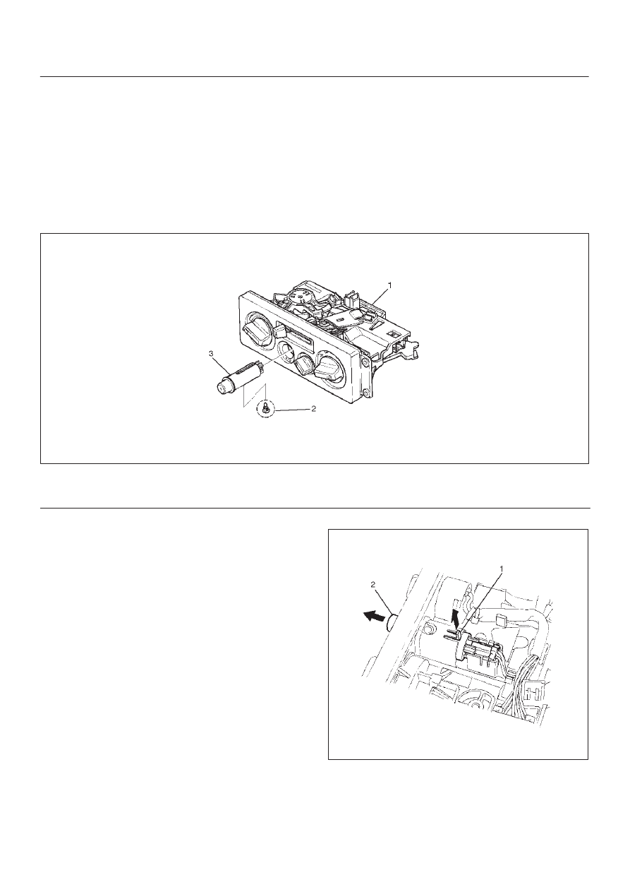
Air Conditioning Switch and Illumination Bulb

Air Conditioning Switch, Illumination Bulb and Associated Parts

865RS003

Legend

(1) Control Lever Assembly

(2) Illumination Bulb
(3) A/C Switch

Removal

1. Disconnect the battery ground cable.
2. Remove control lever assembly.

D

Refer to Control Lever Assembly in this section.

3. Lift up the catch portion (1) of the switch and remove

the air conditioning switch (2) while pushing it toward
the outside.

865RS004

4. Turn the illumination bulb counterclockwise to

remove.

Installation

To install, follow the removal steps in the reverse order.

HEATING, VENTILATION AND AIR CONDITIONING (HVAC) 1A–65

Refrigerant Line

Refrigerant Line and Associated Parts

852R200016

Legend

(1) Clip and Clamp
(2) Suction Line (Low Pressure Hose)
(3) Liquid Line (High-Pressure Pipe)

(4) Discharge Line (High Pressure Hose)
(5) Air Cleaner
(6) Radiator Grille
(7) Suction Line (Low-Pressure Pipe)

Removal

1. Disconnect the battery ground cable.
2. Discharge and recover refrigerant.

D

Refer to Refrigerant Recovery in this section.

3. Remove radiator grille.
4. Remove air cleaner.
5. Remove clip and clamp.
6. Disconnect liquid line (High-pressure pipe).

7. Disconnect suction line (Low-pressure pipe) using a

back-up wrench.

8. Disconnect suction line (Low-pressure hose) using a

back-up wrench.

9. Disconnect discharge line (High-pressure hose)

using a back-up wrench.

D

Use a backup wrench when disconnecting and
reconnecting the refrigerant lines.

1A–66 HEATING, VENTILATION AND AIR CONDITIONING (HVAC)

D

When removing the refrigerant line connecting part,
the connecting part should immediately be plugged
or capped to prevent foreign matter from being
mixed into the line.

Installation

To install, follow the removal steps in the reverse order,
noting the following points:

1. O-rings cannot be reused. Always replace with new

ones. 

2. Be sure to apply new compressor oil to the O-rings

when connecting lines.

3. Tighten the refrigerant line to the specified torque.

Refer to Main Data and Specifications for Torque
Specifications in this section.

HEATING, VENTILATION AND AIR CONDITIONING (HVAC) 1A–67

Main Data And Specifications

General Specifications

Heater Unit

Temperature control

Reheat air mix system

Capacity

4.3 kw (3700 Kcal./hr.)

Air flow

280 m

#

/h

HEATER CORE

Type

Plate and corrugate fin type

Element dimension

171 mm (6.7 in.) 

×

 161 mm (6.3 in.) 

×

 25 mm (0.98 in.)

Radiating area

Approx. 0.75 m

@

EVAPORATOR ASSEMBLY

Capacity

4.9 kw (4200 Kcal./hr.)

Air flow

470 m

#

/hr

EVAPORATOR CORE

Type

Al-laminate louver fin type

Element dimension

235 mm (9.3 in.) 

×

 225.3 mm (8.9 in.) 

×

 60 mm (2.4 in.)

EXPANSION VALVE

Type

Internal pressure equalizer type

THERMOSTAT SWITCH

Type

Electronic thermostat
OFF: Below 1.0

±

0.5

°

C (33.8

±

0.9

°

F)

ON: Above DIFF 2.0

±

0.5

°

C (35.6

±

0.9

°

F)

CONDENSER

Type

Parallel flow type

Radiation performance

16.3 kw (14000 Kcal./hr.)

CONDENSER FAN

Air flow

800 m

3

/h

Fan size

f

252

RECEIVER/DRIER

Type

Assembly includes sight glass with triple pressure
switch

Internal volume

300 cm

3

 (10 fl.oz.)

PRESSURE SWITCH

Type

Triple pressure switch

Low pressure control

ON: 206.0

±

30.0 kPa (29.8

±

4.3 psi)

OFF: 176.5

±

19.6 kPa (25.6

±

2.8 psi)

Medium pressure control

ON: 1471.0

±

98.1 kPa (213.3

±

14.2 psi)

OFF: 1078.7

±

117.7 kPa (156.4

±

17.7 psi)

High pressure control

ON: 2353.6

±

196.1 kPa (341.3

±

28.4 psi)

OFF: 2942.0

±

196.1 kPa (426.6

±

28.4 psi)


Content   ..  547  548  549  550   ..