Isuzu Amigo / Axiom / Trooper / Rodeo / VehiCross. Manual - part 548


  Index      Isuzu     Isuzu Amigo / Axiom / Trooper / Rodeo / VehiCross - service repair manual 1999-2002 year


Search            


Content   ..  546  547  548  549   ..


Isuzu Amigo / Axiom / Trooper / Rodeo / VehiCross. Manual - part 548


1A–60 HEATING, VENTILATION AND AIR CONDITIONING (HVAC)

Pressure Switch

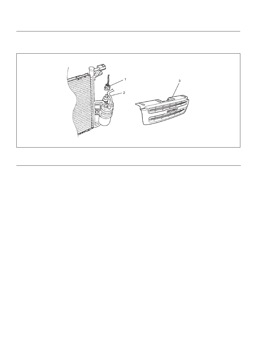
Pressure Switch and Associated Parts

875R200028

Legend

(1) Pressure Switch Connector

(2) Pressure Switch
(3) Radiator Grille

Removal

1. Disconnect the battery ground cable.
2. Discharge and recover refrigerant.

D

Refer to “Refrigerant Recovery in this section.

3. Remove radiator grille.
4. Disconnect pressure switch connector.
5. Disconnect pressure switch.

D

When removing the switch connected part, the
connecting part should immediately be plugged or
capped to prevent foreign matter from being mixed
into the line.

Installation

To install, follow the removal steps in the reverse order,
noting the following point:

1. O-ring cannot be reused. Always replace with a new

one.

2. Be sure to apply new compressor oil to the O-ring

when connecting pressure switch.

3. Tighten the pressure switch to the specified torque.

Torque: 13 N

m (113 lb

in)

HEATING, VENTILATION AND AIR CONDITIONING (HVAC) 1A–61

Evaporator Assembly

Evaporator Assembly and Associated Parts

874RT002

Legend

(1) Resistor and Electronic Thermostat Connector
(2) Drain Hose
(3) Refrigerant Line
(4) Passenger Knee Bolster Reinforcement

Assembly

(5) Instrument Panel Passenger Lower Cover

Assembly

(6) Glove Box
(7) Front Console Assembly
(8) Lower Cluster Assembly
(9) Evaporator Assembly

Removal

1. Disconnect the battery ground cable.
2. Discharge and recover refrigerant.

D

Refer to Refrigerant Recovery in this section.

3. Remove front console assembly.
4. Remove lower cluster assembly.
5. Remove glove box.
6. Remove instrument panel passenger lower cover

assembly.

7. Remove passenger knee bolster reinforcement

assembly.

D

Refer to Instrument Panel Assembly in Body and
Accessories section.

8. Disconnect resistor (2) and electronic thermostat

connector (1).

874RY00009

1A–62 HEATING, VENTILATION AND AIR CONDITIONING (HVAC)

9. Disconnect drain hose.

10. Disconnect refrigerant line.

D

Use a back-up wrench when disconnecting and
reconnecting the refrigerant lines.

D

When removing the refrigerant line connected part,
the connecting part should immediately be plugged
or capped to prevent foreign matter from being
mixed into the line.

11. Remove evaporator assembly.

Installation

To install, follow the removal steps in the reverse order,
noting the following points:

1. To install a new evaporator assembly, add 50cm

3

(1.7 fl. oz.) of new compressor oil to the new core.

2. Tighten the refrigerant outlet line to the specified

torque.

Torque: 25 N

m (18 lb

ft)

3. Tighten the refrigerant inlet line to the specified

torque.

Torque: 15 N

m (11 lb

ft)

4. O-rings cannot be reused. Always replace with new

ones.

5. Be sure to apply new compressor oil to the O-rings

when connecting lines.

Electronic Thermostat, Evaporator Core and/or Expansion Valve

Disassembled View

874R200016

Legend

(1) Lining
(2) Expansion Valve
(3) O-ring
(4) Evaporator Assembly
(5) Lower Case

(6) Lining
(7) Evaporator Core
(8) Electronic Thermostat
(9) Attaching Screw

(10) Upper Case

HEATING, VENTILATION AND AIR CONDITIONING (HVAC) 1A–63

Removal

1. Disconnect the battery ground cable.
2. Discharge and recover refrigerant.

D

Refer to Refrigerant Recovery in this section.

3. Remove evaporator assembly.

D

Refer to Evaporator Assembly in this section.

4. Remove the electronic thermostat sensor.

D

Pull the sensor from the evaporator assembly.

5. Remove attaching screw.
6. Remove upper case.
7. Remove lower case.

D

Slit the case parting face with a knife since the lining
is separated when removing the evaporator.

874RS006

D

Lift to remove the upper case.

874RY00005

8. Remove evaporator core.

874RY00006

9. Remove expansion valve.

D

Tear off the insulator carefully.

D

Remove the sensor fixing clip.

D

Use a back-up wrench when disconnecting all
refrigerant pipes.

Installation

To install, follow the removal steps in the reverse order,
noting the following points:

1. The sensor is installed on the core with the clip.
2. The sensor must not interfere with the evaporator

core.

3. When installing the new evaporator core, install the

thermo sensor (2) to the evaporator core (1) specified
position with the clip in the illustration.

874RX021


Content   ..  546  547  548  549   ..