Isuzu Amigo / Axiom / Trooper / Rodeo / VehiCross. Manual - part 544


  Index      Isuzu     Isuzu Amigo / Axiom / Trooper / Rodeo / VehiCross - service repair manual 1999-2002 year


Search            


Content   ..  542  543  544  545   ..


Isuzu Amigo / Axiom / Trooper / Rodeo / VehiCross. Manual - part 544


1A–44 HEATING, VENTILATION AND AIR CONDITIONING (HVAC)

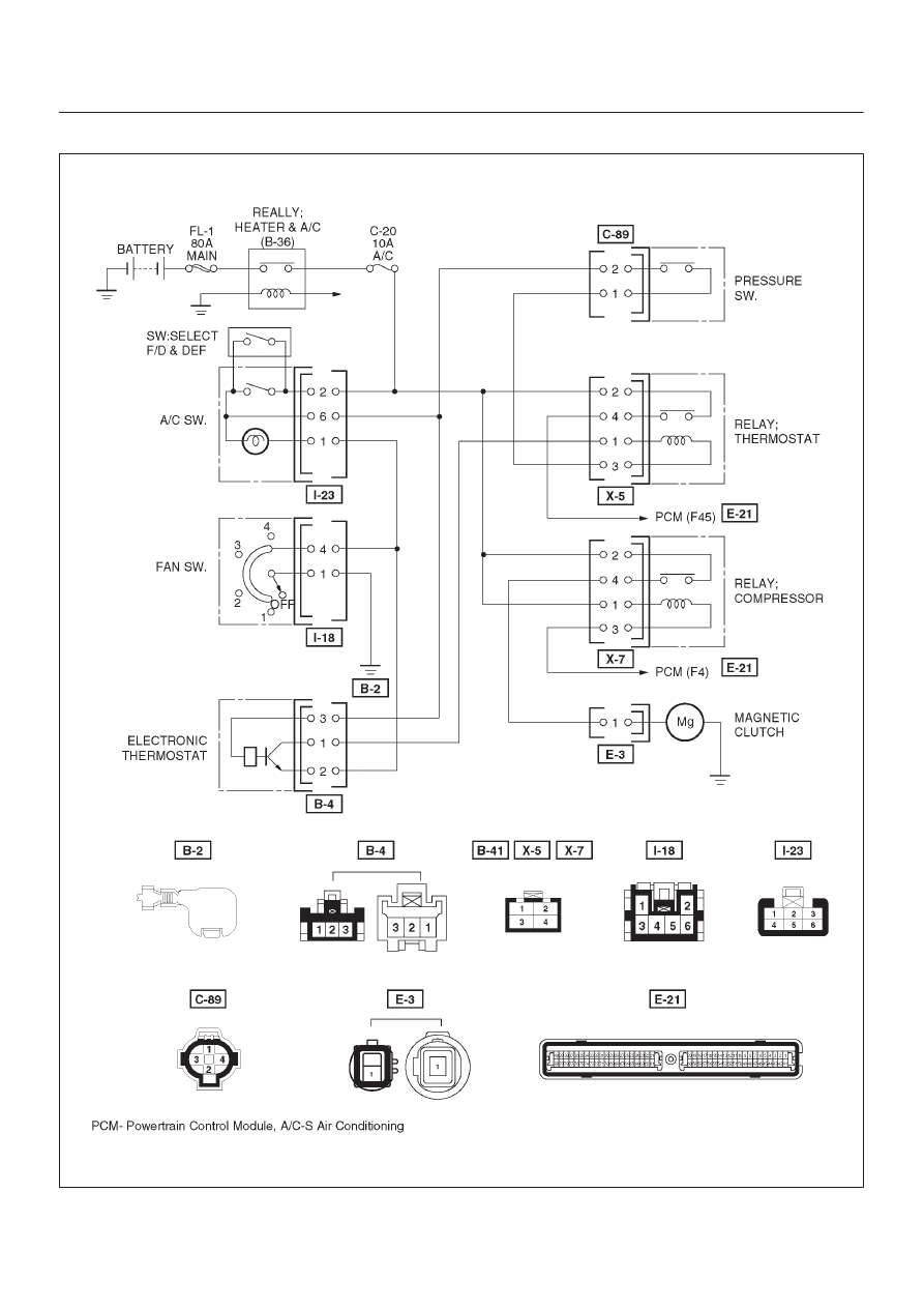
Magnetic Clutch Diagnosis

D08R200260

When the air conditioning switch and the fan control knob
(fan switch) are turned on with the engine running, current

flows through the thermostat and the compressor relay to
activate the magnetic clutch.

HEATING, VENTILATION AND AIR CONDITIONING (HVAC) 1A–45

The air conditioning can be stopped by turning off the air
conditioning switch or the fan control knob (fan switch).
However, even when the air conditioning is in operation,
the electronic thermostat, the pressure switch or the
Powertrain Control Module (PCM) is used to stop the air
conditioning temporarily by turning off the magnetic clutch

in the prearranged conditions to reduce the engine load
which is being caused by the rise in the engine coolant
temperature, and the acceleration of the vehicle, etc.
For the inspection of the relays, switches and units in the
table, refer to “Individual Inspection” in this section.

Magnetic Clutch Does Not Run 

Step

Action

Yes

No

1

Are No. C-20 (10A) fuse and No. C-19 (25A) fuse OK?

Go to Step 2

Replace

2

Are heater and A/C (B-36), thermostat (X-5), and compressor
(X-7) relays OK?

Go to Step 3

Replace

3

Is pressure switch (triple pressure switch) OK?

Go to Step 4

Switch defective

or insufficient

refrigerant.

4

Are air conditioning switch and fan control knob (Fan Switch) OK?

Go to Step 5

Replace

5

1. Turn the ignition switch “ON” (Engine is running).
2. Air conditioning switch and fan control knob (Fan Switch)

“ON”.

3. Check to see if battery voltage is present at chassis side

connector terminal No. E3-1.

Is there a battery voltage?

Go to Step 6

Go to Step 7

6

Check to see if continuity between compressor side connector
terminal No. E3-1 and the magnetic clutch side connector
terminal.

Is there a continuity?

Magnetic clutch

defective.

Compressor

defective.

7

Check to see if battery voltage is present at chassis side
connector terminal No. C89-2

Is there a battery voltage?

Go to Step 8

Open circuit

between No.C-20

(10A) fuse and

No. C89-2.

8

1. Disconnect thermostat relay (X-5).
2. Check to see if battery voltage is present at the chassis side

relay terminal NO. X5-2

Is there a battery voltage?

Go to Step 9

Open circuit

between No.

C89-1 and

No.X5-2.

9

Check to see if voltage (approx. 10V) is present between chassis
side relay terminal No. X5-1 and No. X5-3.

Is there a battery voltage?

Go to Step 10

Go to Step 16

10

1. Reconnect thermostat relay and disconnect compressor relay

(X-7).

2. Check to see if battery voltage is present at the chassis side

relay terminal No. X7-2.

Is there a battery voltage?

Go to Step 11

Open circuit

between No.

X5-4 and No.

X7-2.

11

Check to see if continuity between chassis side relay terminal No.
X7-4 and the chassis side connector terminal No. E3-1.

Is there a continuity?

Go to Step 12

Open circuit.

12

Check to see if battery voltage is present between chassis side
relay terminal No. X7-1 and No. X7-3.

Is there a battery voltage?

Go to Step 13

Go to Step 14

13

Check to see if battery voltage is present at chassis side relay
terminal No. X7-1.

Is there a battery voltage?

Go to Step 15

Open circuit

between No.

C-20 (10A) fuse

and No. X7-1.

1A–46 HEATING, VENTILATION AND AIR CONDITIONING (HVAC)

Magnetic Clutch Does Not Run  (Cont’d)

Step

No

Yes

Action

14

Check to see if battery voltage is present at chassis side
connector terminal No. E21-F4.

Is there a battery voltage?

Power train

control module

(PCM) defective.

Refer to

Driveability and

Emissions in

Engine section.

Open circuit

between No.

X7-3 and No.

E21-F4.

15

Check to see if continuity between chassis side relay terminal No.
X5-4 and chassis side connector terminal No. E21-F45.

Is there a continuity?

Power train

control module

(PCM) defective.

Refer to

Driveability and

Emissions in

Engine section.

Open circuit

16

Check to see if battery voltage is present at chassis side relay
terminal No. X5-1.

Is there a battery voltage?

Go to Step 17

Go to Step 20

17

1. Reconnect thermostat relay.
2. Check to see if battery voltage is present at chassis side

connector terminal No. B4-3.

Is there a battery voltage?

Go to Step 18

Open circuit

between No.I23-6

and No.B4-3.

18

Check to see if battery voltage (appox 10V) is present at chassis
side connector terminal No. B4-1.

Is there a battery voltage?

Go to Step 19

Open circuit

between No.

X5-3 and No.

B4-1.

19

Check to see if continuity between chassis side connector
terminal No. B4-2 and No. I18-4.

Is there a continuity?

Electronic

thermostat

defective.

Open circuit

between No.

B4-2 and No.

I18-4 or poor

ground (Fan

Switch Ground

Circuit).

20

Check to see if battery voltage is present at chassis side
connector terminal No. I23-2.

Is there a battery voltage?

Open circuit

between X5-1

and No.I23-6.

Open circuit

between No.

C-20 (10A) fuse

and No.I23-2.

HEATING, VENTILATION AND AIR CONDITIONING (HVAC) 1A–47

Individual Inspection

Fan Control Knob (Fan Switch) And Air
Conditioning (A/C) Switch

1. Check for continuity between the fan switch and the

A/C switch side connector terminals.

865RS002

Fan swtich

position

Fan switch connector terminals with

continuity

OFF

No continuity

1

1 – 2 – 4

2

1 – 4 – 5

3

1 – 3 – 4

4

1 – 4 – 6

A/C switch

position

A/C switch connector terminals with

continuity

OFF

1 – 6

ON

1 – 2 – 6

Heater And A/C (B-36), Thermostat (X-5)
And Compressor (X-7) Relay

1. Disconnect relays and check for continuity and

resistance between relay terminals.

D

For handling of these relays, refer to Heater &A/C
Relay in this section.

825RS003

Condition

Relay terminals with con-

tinuity

Normal

1 – 3 (Approx 85–105

W

)

When battery voltage is

applied between 1 – 3

2 – 4


Content   ..  542  543  544  545   ..