Isuzu Amigo / Axiom / Trooper / Rodeo / VehiCross. Manual - part 541


  Index      Isuzu     Isuzu Amigo / Axiom / Trooper / Rodeo / VehiCross - service repair manual 1999-2002 year


Search            


Content   ..  539  540  541  542   ..


Isuzu Amigo / Axiom / Trooper / Rodeo / VehiCross. Manual - part 541


1A–32 HEATING, VENTILATION AND AIR CONDITIONING (HVAC)

The refrigeration cycle includes the following four
processes as the refrigerant changes repeatedly from
liquid to gas and back to liquid while circulating.

Evaporation

The refrigerant is changed from a liquid to a gas inside the
evaporator.  The refrigerant mist that enters the
evaporator vaporizes readily. The liquid refrigerant
removes the required quantity of heat (latent heat of
vaporization) from the air around the evaporator core
cooling fins and rapidly vaporizes.  Removing the heat
cools the air, which is then radiated from the fins and
lowers the temperature of the air inside the vehicle.
The refrigerant liquid sent from the expansion valve and
the vaporized refrigerant gas are both present inside the
evaporator as the liquid is converted to gas.
With this change from liquid to gas, the pressure inside
the evaporator must be kept low enough for vaporization
to occur at a lower temperature.  Because of that, the
vaporized refrigerant is sucked into the compressor.

Compression

The refrigerant is compressed by the compressor until it is
easily liquefied at normal temperature.
The vaporized refrigerant in the evaporator is sucked into
the compressor.  This action maintains the refrigerant
inside the evaporator at a low pressure so that it can
easily vaporize, even at low temperatures close to
0

°

C(32

°

F).

Also, the refrigerant sucked into the compressor is
compressed inside the cylinder to increase the pressure
and temperature to values such that the refrigerant can
easily liquefy at normal ambient temperatures.

Condensation

The refrigerant inside the condenser is cooled by the
outside air and changes from gas to liquid.
The high temperature, high pressure gas coming from the
compressor is cooled and liquefied by the condenser with
outside air and accumulated in the receiver/drier. The
heat radiated to the outside air by the high temperature,
high pressure gas in the compressor is called heat of
condensation. This is the total quantity of heat (heat of
vaporization) the refrigerant removes from the vehicle
interior via the evaporator and the work (calculated as the
quantity of heat) performed for compression.

Expansion

The expansion valve lowers the pressure of the
refrigerant liquid so that it can easily vaporize.
The process of lowering the pressure to encourage
vaporization before the liquefied refrigerant is sent to the
evaporator is called expansion. In addition, the expansion
valve controls the flow rate of the refrigerant liquid while
decreasing the pressure.
That is, the quantity of refrigerant liquid vaporized inside
the evaporator is determined by the quantity of heat which
must be removed at a prescribed vaporization
temperature. It is important that the quantity of refrigerant
be controlled to exactly the right value.
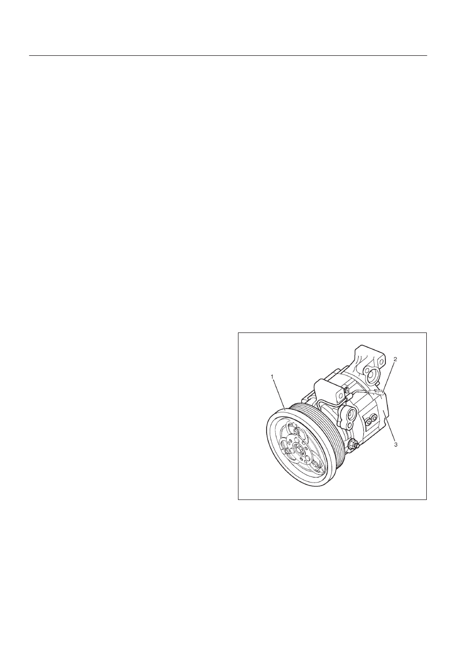
Compressor

The compressor performs two main functions:
It compresses low-pressure and low-temperature
refrigerant vapor from the evaporator into high-pressure
and high-temperature refrigerant vapor to the condenser.
It pumps refrigerant and refrigerant oil through the air
conditioning system.
This vehicle is equipped with six-cylinder axle plate
compressor (3).
The specified amount of the compressor oil is 240cm

3

(8.0 fl. oz.).
The oil used in the HFC-134a system compressor differs
from that used in R-12 systems.
Also, compressor oil to be used varies according to the
compressor model.  Be sure to avoid mixing two or more
different types of oil.
If the wrong oil is used, lubrication will be poor and the
compressor will seize or malfunction.
The magnetic clutch connector is a waterproof type.

Magnetic Clutch

The compressor is driven by the drive belt from the crank
pulley of the engine. If the compressor is activated each
time the engine is started, this causes too much load to
the engine. The magnetic clutch (1) transmits the power
from the engine to the compressor and activates it when
the air conditioning is ON. Also, it cuts off the power from
the engine to the compressor when the air conditioning is
OFF. Refer to Compressor in this section for magnetic
clutch repair procedure.

871R200002

Condenser

Also, it functions to cool and liquefy the high-pressure and
high-temperature vapor sent from the compressor by the
radiator fan or outside air.
A condenser may malfunction in two ways: it may leak, or
it may be restricted.  A condenser restriction will result in
excessive compressor discharge pressure.  If a partial
restriction is present, the refrigerant expands after
passing through the restriction.
Thus, ice or frost may form immediately after the
restriction. If air flow through the condenser or radiator is

HEATING, VENTILATION AND AIR CONDITIONING (HVAC) 1A–33

blocked, high discharge pressures will result. During
normal condenser operation, the refrigerant outlet line will
be slightly cooler than the inlet line.
The vehicle is equipped with the parallel flow type
condenser. A larger thermal transmission area on the
inner surface of the tube allows the radiant heat to
increase and the ventilation resistance to decrease.
The refrigerant line connection has a bolt at the block
joint, for easy servicing.
The condenser assembly (3) is located in front of the
radiator. It provides rapid heat transfer from the
refrigerant to the cooling fins.

875R200025

Receiver / Drier

The receiver/drier (2) performs four functions:

D

As the quantity of refrigerant circulated varies
depending on the refrigeration cycle conditions,
sufficient refrigerant is stored for the refrigeration
cycle to operate smoothly in accordance with
fluctuations in the quantity circulated.

D

The liquefied refrigerant from the condenser is mixed
with refrigerant gas containing air bubbles. If
refrigerant containing air bubbles. Is sent to the
expansion valve, the cooling capacity will decrease
considerably. Therefore, the liquid and air bubbles are
separated and only the liquid is sent to the expansion
valve.

D

The receiver/drier utilizes a filter and drier to remove
the dirt and water mixed in the cycling refrigerant.

D

The sight glass, installed on top of the receiver/drier,
shows the state of the refrigerant.

A receiver/drier may fail due to a restriction inside the
body of the unit. A restriction at the inlet to the
receiver/drier will cause high pressure.
Outlet restrictions will be indicated by low pressure and
little or no cooling. An excessively cold receiver/drier
outlet may indicate a restriction.
The receiver/drier of this vehicle is made of aluminum
with a smaller tank. It has a 300cc refrigerant capacity.
The refrigerant line connection has a bolt at the block
joint, for easy servicing.

875R200025

Triple Pressure Switch

Triple pressure switch is installed on the upper part of the
receiver/drier. This switch is constructed with a unitized
type of two switches. One of them is a low and high
pressure switch (Dual pressure switch) to switch “ON” or
“OFF” the magnetic clutch as a result of irregularly
high–pressure or low pressure of the refrigerant. The
other one is a medium pressure switch (Cycling switch) to
switch “ON” or “OFF” the condenser fan sensing the
condenser high side pressure.

Compressor

ON

(kPa/psi)

OFF

(kPa/psi)

Low-pressure

control

206.0

±

30.0

(29.8

±

4.3)

176.5

±

24.5

(25.6

±

3.6)

High-pressure

control

2353.6

±

196.1

(341.3

±

28.4)

2942.0

±

196.1

(426.6

±

28.4)

Condenser fan

ON

(kPa/psi)

OFF

(kPa/psi)

Medium-pressure

control

1471.0

±

98.1

(213.3

±

14.2)

1078.7

±

117.7

(156.4

±

17.1)

1A–34 HEATING, VENTILATION AND AIR CONDITIONING (HVAC)

875R200025

Expansion Valve

This expansion valve (1) is an internal pressure type and it
is installed at the evaporator intake port.
The expansion valve converts the high pressure liquid
refrigerant sent from the receiver/drier to a low pressure
liquid refrigerant by forcing it through a tiny port before
sending it to the evaporator (2).
This type of expansion valve consists of a temperature
sensor, diaphragm, ball valve, ball seat, spring
adjustment screw, etc.
The temperature sensor contacts the evaporator outlet
pipe, and converts changes in temperature to pressure.  It
then transmits these to the top chamber of the
diaphragm.
The refrigerant pressure is transmitted to the diaphragm’s
bottom chamber through the external equalizing pressure
tube.
The ball valve is connected to the diaphragm. The
opening angle of the expansion valve is determined by
the force acting on the diaphragm and the spring
pressure.
The expansion valve regulates the flow rate of the
refrigerant. Accordingly, when a malfunction occurs to
this expansion valve, both discharge and suction
pressure get low, resulting in insufficient cooling capacity
of the evaporator.
The calibration has been changed to match the
characteristics of HFC-134a.

874RY00003

Evaporator

The evaporator cools and dehumidifies the air before the
air enters the passenger compartment. High-pressure
liquid refrigerant flows through the expansion valve (2)
into the low-pressure area of the evaporator. The heat in
the air passing through the evaporator core (1) is lost to
the cooler surface of the core, thereby cooling the air.
As heat is lost between the air and the evaporator core
surface, moisture in the vehicle condenses on the outside
surface of the evaporator core and is drained off as water.
When the evaporator malfunctions, the trouble will show
up as an inadequate supply of cool air. The cause is
typically a partially plugged core due to dirt, or a
malfunctioning blower motor.
The evaporator core with a laminate louver fin is a
single-sided tank type where only one tank is provided
under the core.

874RY00007

HEATING, VENTILATION AND AIR CONDITIONING (HVAC) 1A–35

Electronic Thermostat

The thermostat consists of the thermo sensor (1) and
thermostat unit (4) which functions electrically to reduce
the noises being generated while the system is in
operation.
The electronic thermo sensor (1) is mounted at the
evaporator core (2) outlet and senses the temperature of
the cool air from the evaporator (3). Temperature signals
are input to the thermostat unit. This information is
compared by the thermo unit and results in the output to
operate the A/C thermostat relay and turn the magnetic
clutch ON or OFF to prevent evaporator freeze-up.
A characteristic of the sensor is that the resistance
decreases as the temperature increases and the
resistance increases as the temperature decreases.

874RX022

Refrigerant Line

Restriction in the refrigerant line will be indicated by:

1. Suction line — A restricted suction line will cause low

suction pressure at the compressor, low discharge
pressure and little or no cooling.

2. Discharge line — A restriction in the discharge line

generally will cause the discharge line to leak.

3. Liquid line — A liquid line restriction will be evidenced

by low discharge and suction pressure and
insufficient cooling.

Refrigerant flexible hoses that have a low permeability to
refrigerant and moisture are used. These low
permeability hoses have a special nylon layer on the
inside.

852RW011

Legend

(1) Pressure Resistance Layer (Polyester Braid)
(2) Moisture Resistance AND Outer Protector

Layer

(3) Heat Resistance Layer
(4) Heat Resistance Core Layer (Neoprene)
(5) Low Permeation Layer (Nylon Barner)


Content   ..  539  540  541  542   ..