Isuzu Amigo / Axiom / Trooper / Rodeo / VehiCross. Manual - part 513
SUPPLEMENTAL RESTRAINT SYSTEM
9J–35
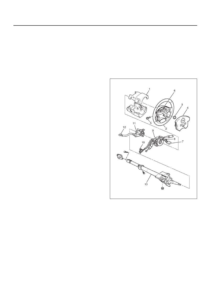
Installation
1. Install the steering column assembly (13) and align
the setting marks on the universal joint and steering
shaft made during removal.
2. Tighten the steering column fixing bolts (dash panel
side) to the specified torque.
Torque: 20 N·m (14 lb ft)
3. Tighten the steering column fixing nuts (Cross beam)
to the specified torque.
Torque: 20 N·m (14 lb ft)
4. Tighten the universal joint to the specified torque.
Torque: 31 N·m (23 lb ft)
5. Install steering lock cylinder assembly (11).
6. Connect shift lock cable (For A/T)
7. Install cushion rubber.
8. Install snap ring.
9. Install the combination switch assembly with SRS coil
(9).
10. Connect the wiring harness connector (10) located on
the base of steering column.
11. Turn the SRS coil clockwise to full, return about 3
turns and align the neutral mark.
CAUTION: When turning the SRS coil clockwise to
full, stop turning if resistance is felt. Further forced
turning may damage the cable in the SRS coil.
12. Install steering column cover (1).
CAUTION: When installing the steering column
cover, be sure to wire (through each harness) as
illustrated so that the harnesses starter switch,
combination switch and SRS coil may not catch
wiring.
13. Install the steering wheel (2) and align the setting
marks (6).
14. Tighten the steering wheel fixing nut (3) to the
specified torque.
Torque: 34 N·m (25 lb ft)
15. Connect horn lead (8).
16. Connect air Bag wiring harness connector (7).
NOTE: Pass the lead wire through the tabs on the plastic
cover (wire protector) of air bag to prevent lead wire from
being pinched.
17. Install air bag into steering wheel and tighten bolts (5)
to specified sequence as shown in figure.
Torque: 8.8 N·m (78 lb in)
CAUTION: Never use the air bag assembly from
another vehicle and difference model year air bag
assembly.
The air bag assembly has identification colors on the
bar code label as follows.
Light blue color for driver air bag assembly.
Light blue color for passenger air bag assembly.
Use only the air bag assembly for “UP”.
431R200004
18. Enable the SRS (Refer to “Enabling The SRS” in this
section.)