Isuzu Amigo / Axiom / Trooper / Rodeo / VehiCross. Manual - part 478


  Index      Isuzu     Isuzu Amigo / Axiom / Trooper / Rodeo / VehiCross - service repair manual 1999-2002 year


Search            


Content   ..  476  477  478  479   ..


Isuzu Amigo / Axiom / Trooper / Rodeo / VehiCross. Manual - part 478


8F–33

BODY STRUCTURE

Removal

CAUTION: For precautions on installation or
removal of SRS – air bag system, refer to
Supplemental Restraint  System (SRS) – AIR BAG in
Restraint section.

1. Disconnect the battery ground cable.
2. Pry the knee pads (4).
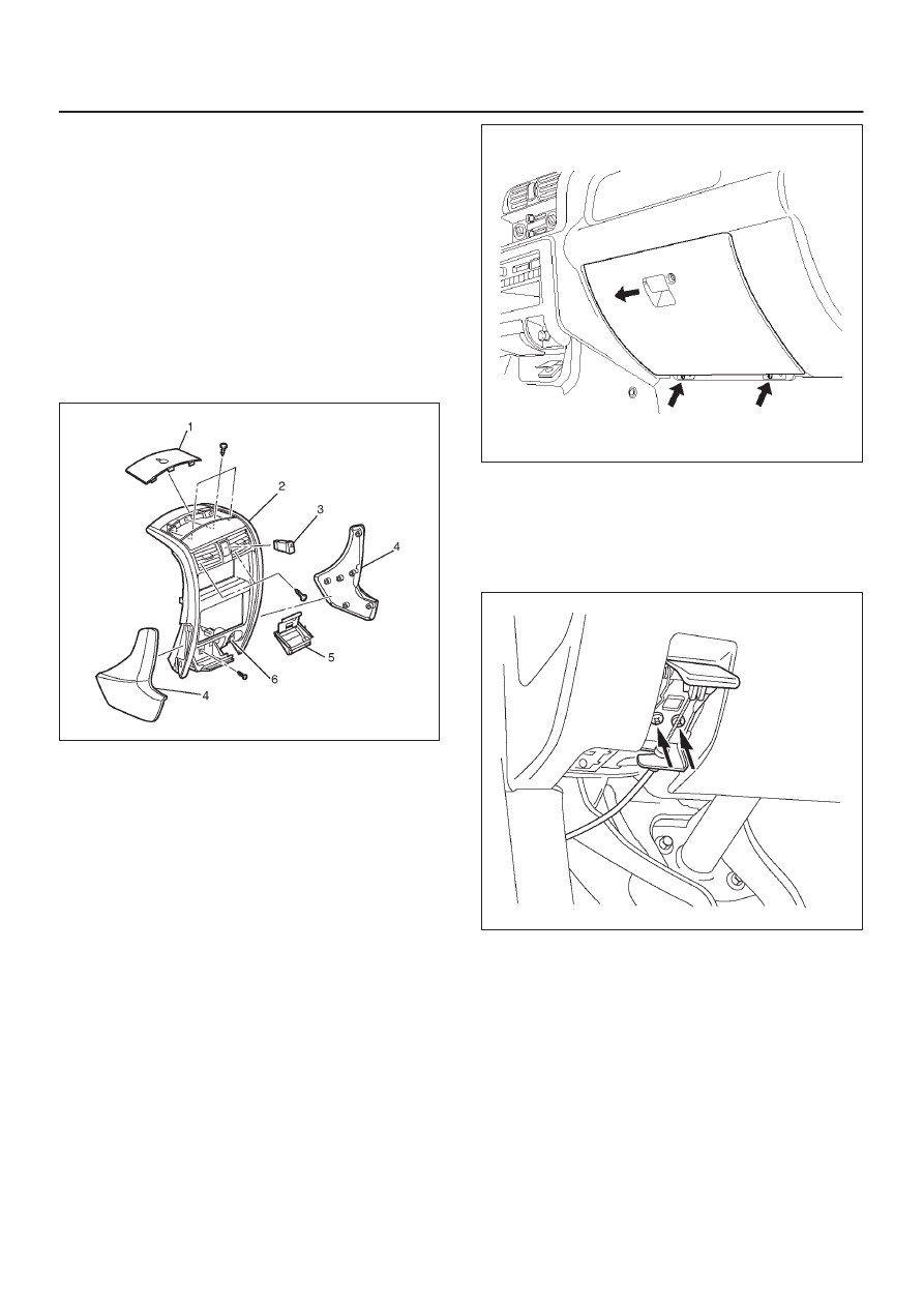
3. Remove the cluster upper cover (1) and connectors.
4. Remove the center cluster assembly (2).

D

Remove six screws and pull out the cluster at the six
clip positions.

D

Disconnect the cigarette lighter (6), ash tray (5)
illumination and hazard switch (3) connectors.

740R200008

5. Remove the display unit.

D

Remove the four fixing screws and connectors.

6. Remove the audio kit.

D

Remove the four fixing screws and connectors.

7. Remove the front and rear consoles.

D

Refer to 

Consoles in Exterior/Interior Trim section.

8. Remove the dash side trim panels.

D

Remove the sill plates, then remove the trim panels.

9. Remove the glove box.

D

Remove the two fixing screws.

470RW002

10. Remove the instrument panel driver lower cover

assembly.

D

Remove the engine hood opener two fixing screws
and another one fixing screw.
After four clips are pried, disconnect switch
connector and duct.

610R200007

11. Remove the meter cluster assembly.

D

Remove the six fixing screws and switch
connectors.

12. Remove the meter assembly.

D

Remove the four fixing screws and disconnect the
connectors.

13. Remove the driver knee bolster assembly.

D

Remove the six fixing bolts and screw.

14. Remove the instrument panel assembly.

CAUTION: For precautions on installation or
removal of SRS – air bag system, refer to
Supplemental  Restraint System (SRS) – AIR BAG in
Restraint section.

8F–34

BODY STRUCTURE

D

Disconnect the instrument harness connectors (six
connectors on the driver’s side, three connectors
on the passenger side and two connectors on the
center side).

D

Disconnect radio antenna cable plug and the
ground cable fixing bolts from dash side panel.

D

Remove the two fixing bolts of passenger air bag
assembly and disconnect the connector.

D

Remove the two fixing screws from fuse box.

D

After pry the three hole cover from the surface of
instrument panel, remove the three nuts.

D

Remove the six bolts and one screw.

740R200022

15. Remove the passenger air bag (1).

D

Remove the four fixing nuts.

CAUTION: For precautions on installation or
removal of SRS – air bag system, refer to
Supplemental  Restraint System in Restraint section.

827RY00004

16. Remove the vent duct assembly.

D

Remove the five fixing screws.

17. Remove the passenger lower bracket.

D

Remove the three screws.

18. Remove the glove box side reinforcement.
19. Remove the instrument upper reinforcement.

D

Remove the nine screws.

20. Remove the instrument panel center reinforcement.

D

Remove the six screws.

21. Remove the instrument panel harness assembly (1).

D

Remove the clips.

740R200023

22. Remove the instrument panel stays.

D

Remove the two fixing nuts and two fixing bolts for
each bracket.

23. Remove the cross beam.

D

Remove the five fixing nuts, two fixing bolts (upper)
and six fixing bolts (lower).

840RW005

Installation

To install, follow the removal steps in the reverse order.

8F–35

BODY STRUCTURE

Front Door Assembly

Parts Location

630R200010

Legend

(1) Front Door Assembly
(2) Upper Hinge Bolt

(3) Door Harness Connector
(4) Door Check Arm
(5) Lower Hinge Bolt

Removal

1. Disconnect the battery ground cable.
2. Apply a setting mark on the body side hinge.
3. Remove the door check arm bolt.

630R200011

8F–36

BODY STRUCTURE

4. Remove the upper and lower hinge bolts.

D

Position a wood block under the door for protection
and support the door assembly with hands during
removal or installation.

635R200013

5. Remove the door harness connector.

D

Pull the door harness grommet out in order to
disconnect the harness connector.

630R200012

6. Remove the front door assembly.

Installation

To install, follow the removal steps in the reverse order,
noting the following points:

1. Align the door fitting to the body.

D

Check the fender and front door (1).

Clearance: 5.0 mm (0.196 in)

Height (step): Flush

D

Check the front door and rear door (2).

Clearance: 5.0 mm (0.196 in)

Height (step): Flush

D

Check the rear door and body (3).

Clearance: 5.0 mm (0.196 in)

Height (step): Flush

Adjust clearance with door hinges.
Adjust height (step) by tapping on the fender lightly
with a rubber hammer.

610R200005

2. Tighten the door hinge bolts to the specified torque.

Torque : 34 N·m (25 lb ft)

3. Tighten the door check arm bolt and nuts to the

specified torque.

Torque : 9 N·m (78 lb in)


Content   ..  476  477  478  479   ..