Isuzu Amigo / Axiom / Trooper / Rodeo / VehiCross. Manual - part 414
7A–69
AUTOMATIC TRANSMISSION (4L30–E)
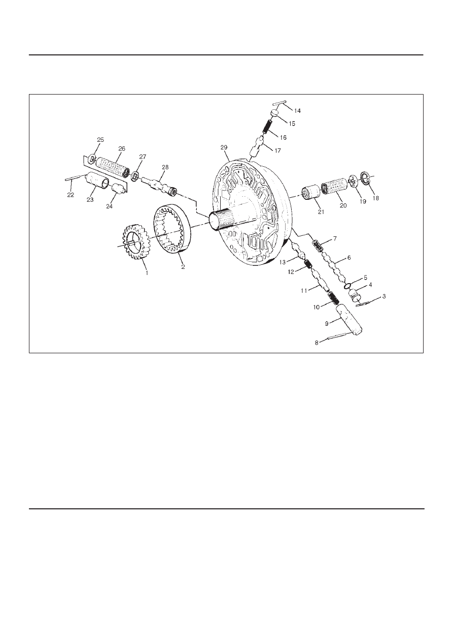
Oil Pump
Disassembled View
241RY002
Legend
(1) Oil Pump Drive Gear
(2) Oil Pump Driven Gear
(3) Pin
(4) Plug
(5) Seal Ring
(6) Torque Converter Clutch Control Valve
(7) Converter Clutch Control Valve Spring
(8) Pin
(9) Converter Clutch Regulator Sleeve
(10)
Converter Clutch Regulator Spring
(11)
Converter Clutch Regulator Valve
(12)
Isolator Spring
(13)
Isolator Valve
(14)
Pin
(15)
Enable Valve Spring Guide
(16)
Enable Valve Spring
(17)
Enable Valve
(18)
Snap Ring
(19)
Spring Seat
(20)
Throttle Signal Accumulator Spring
(21)
Throttle Signal Accumulator Piston
(22)
Sleeve Pin
(23)
Boost Valve Sleeve
(24)
Boost Valve
(25)
Spring Seat
(26)
Pressure Regulator Valve Spring
(27)
Spring Seat
(28)
Pressure Regulator Valve
(29)
Oil Pump Assembly
Disassembly
1. Remove oil pump drive gear (1) and driven gear (2).
2. Remove pin (3) from oil pump assembly (29).
3. Remove plug (4) and seal ring (5), torque converter
clutch control valve (6) and spring (7).
4. Remove pin (8) from oil pump assembly (29).
5. Remove torque converter regulator sleeve (9),
converter clutch regulator spring (10), converter
clutch regulator valve (11), isolator spring (12) and
isolator valve (13).
6. Remove pin (14) from oil pump assembly (29).
7. Remove enable valve spring (16), spring guide (15)
and enable valve (17).
8. Remove snap ring (18) from oil pump assembly (29).