Isuzu Amigo / Axiom / Trooper / Rodeo / VehiCross. Manual - part 386


  Index      Isuzu     Isuzu Amigo / Axiom / Trooper / Rodeo / VehiCross - service repair manual 1999-2002 year


Search            


Content   ..  384  385  386  387   ..


Isuzu Amigo / Axiom / Trooper / Rodeo / VehiCross. Manual - part 386


6E–574

6VE1 3.5L ENGINE DRIVEABILITY AND EMISSIONS

resistance of 100,000 ohms at –40

°

C (–40

°

F).  High

temperature causes low resistance of 70 ohms at 130

°

C

(266

°

F) .  The PCM supplies a 5-volt signal to the sensor

through a resistor in the PCM and monitors the signal
voltage.  The voltage will be high when the incoming air is
cold.  The voltage will be low when the incoming air is hot.
By measuring the voltage, the PCM calculates the
incoming air temperature.  The IAT sensor signal is used
to adjust spark timing according to the incoming air
density.
The Tech 2 displays the temperature of the air entering
the engine.  The temperature should read close to the
ambient air temperature when the engine is cold and rise
as underhood temperature increases.  If the engine has
not been run for several hours (overnight), the IAT sensor
temperature and engine coolant temperature should read
close to each other.  A fault in the IAT sensor circuit will set
DTC P0112 or DTC P0113.

Linear Exhaust Gas Recirculation (EGR)
Control

The PCM monitors the exhaust gas recirculation (EGR)
actual position and adjusts the pintle position accordingly.
The PCM uses information from the following sensors to
control the pintle position:

D

Engine coolant temperature (ECT) sensor.

D

Throttle position (TP) sensor.

D

Mass air flow (MAF) sensor.

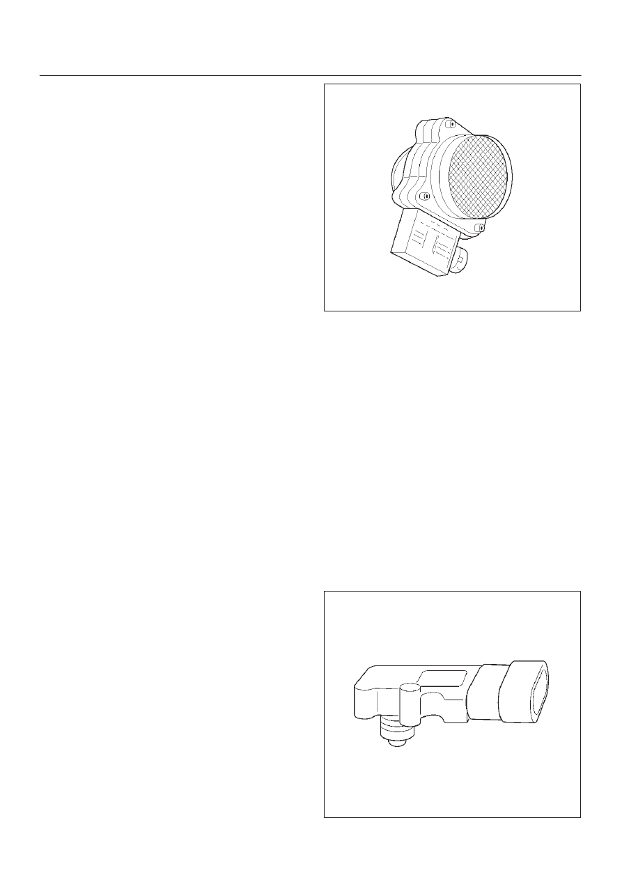
Mass Air Flow (MAF) Sensor

The mass air flow (MAF) sensor measures the difference
between the volume and the quantity of air that enters the
engine.  “Volume” means the size of the space to be filled.
“Quantity” means the number of air molecules that will fit
into the space.  This information is important to the PCM
because heavier, denser air will hold more fuel than
lighter, thinner air.  The PCM adjusts the air/fuel ratio as
needed depending on the MAF value.  The Tech 2 reads
the MAF value and displays it in terms of grams per
second (gm/s).  At idle, the Tech 2 should read between
4-7 gm/s on a fully warmed up engine.  Values should
change quickly on acceleration.  Values should remain
stable at any given RPM.  A failure in the MAF sensor or
circuit will set DTC P0101, DTC P0102, or DTC P0103.

0007

Manifold Absolute Pressure (MAP) Sensor

The manifold absolute pressure (MAP) sensor responds
to changes in intake manifold pressure (vacuum).  The
MAP sensor signal voltage to the PCM varies from below
2 volts at idle (high vacuum) to above 4 volts with the
ignition ON, engine not running or at wide-open throttle
(low vacuum).
The MAP sensor is used to determine the following:

D

Manifold pressure changes while the linear EGR flow
test diagnostic is being run.  Refer to 

DTC P0401.

D

Barometric pressure (BARO).

If the PCM detects a voltage that is lower than the
possible range of the MAP sensor, DTC P0107 will be set.
A signal voltage higher than the possible range of the
sensor will set DTC P0108.  An intermittent low or high
voltage will set DTC P1107, respectively.  The PCM can
detect a shifted MAP sensor.  The PCM compares the
MAP sensor signal to a calculated MAP based on throttle
position and various engine load factors.  If the PCM
detects a MAP signal that varies excessively above or
below the calculated value, DTC P0106 will set.

055RW004

6E–575

6VE1 3.5L ENGINE DRIVEABILITY AND EMISSIONS

Powertrain Control Module (PCM)

The powertrain control module (PCM) is located in the
passenger compartment below the center console.  The
PCM controls the following:

D

Fuel metering system.

D

Transmission shifting (automatic transmission only).

D

Ignition timing.

D

On-board diagnostics for powertrain functions.

The PCM constantly observes the information from
various sensors.  The PCM controls the systems that
affect vehicle performance.  The PCM performs the
diagnostic function of the system.  It can recognize
operational problems, alert the driver through the MIL
(Check Engine lamp), and store diagnostic trouble codes
(DTCs).  DTCs identify the problem areas to aid the
technician in making repairs.

PCM Function

The PCM supplies either 5 or 12 volts to power various
sensors or switches.  The power is supplied through
resistances in the PCM which are so high in value that a
test light will not light when connected to the circuit.  In
some cases, even an ordinary shop voltmeter will not give
an accurate reading because its resistance is too low.
Therefore, a digital voltmeter with at least 10 megohms
input impedance is required to ensure accurate voltage
readings. Tool J 39200 meets this requirement.  The PCM
controls output circuits such as the injectors, fan relays,
etc., by controlling the ground or the power feed circuit
through transistors or through either of the following two
devices:

D

Output Driver Module (ODM)

D

Quad Driver Module (QDM)

060RY00068

PCM Components

The PCM is designed to maintain exhaust emission levels
to government mandated standards while providing
excellent driveability and fuel efficiency.  The PCM
monitors numerous engine and vehicle functions via
electronic sensors such as the throttle position (TP)

sensor, heated oxygen sensor (HO2S), and vehicle
speed sensor (VSS).  The PCM also controls certain
engine operations through the following:

D

Fuel injector control

D

Ignition control module

D

ION sensing module

D

Automatic transmission shift functions

D

Cruise control

D

Evaporative emission (EVAP) purge

D

A/C clutch control

PCM Voltage Description

The PCM supplies a buffered voltage to various switches
and sensors.  It can do this because resistance in the
PCM is so high in value that a test light may not illuminate
when connected to the circuit.  An ordinary shop
voltmeter may not give an accurate reading because the
voltmeter input impedance is too low.  Use a 10-megohm
input impedance digital voltmeter (such as J 39200) to
assure accurate voltage readings.
The input/output devices in the PCM include
analog-to-digital converters, signal buffers, counters,
and special drivers.  The PCM controls most components
with electronic switches which complete a ground circuit
when turned “ON.”  These switches are arranged in
groups of 4 and 7, called either a surface-mounted quad
driver module (QDM), which can independently control up
to 4 output terminals, or QDMs which can independently
control up to 7 outputs.  Not all outputs are always used.

PCM Input/Outputs

Inputs – Operating Conditions Read

D

Air Conditioning “ON” or “OFF” 

D

Engine Coolant Temperature

D

Crankshaft Position

D

Exhaust Oxygen Content

D

Electronic Ignition

D

Manifold Absolute Pressure

D

Battery Voltage

D

Throttle Position

D

Vehicle Speed

D

Fuel Pump Voltage

D

Power Steering Pressure

D

Intake Air Temperature

D

Mass Air Flow

D

Engine Knock

D

Acceleration Position

Outputs – Systems Controlled

D

EVAP Canister Purge

D

Exhaust Gas Recirculation (EGR)

D

Ignition Control

D

Fuel Control

D

ION Sensing Module

D

Electric Fuel Pump

D

Air Conditioning

6E–576

6VE1 3.5L ENGINE DRIVEABILITY AND EMISSIONS

D

Diagnostics
– Malfunction Indicator Lamp
– Data Link Connector (DLC)
– Data Output

D

Transmission Control Module

PCM Service Precautions

The PCM is designed to withstand normal current draws
associated with vehicle operation.  Avoid overloading any
circuit.  When testing for opens and shorts, do not ground
or apply voltage to any of the PCM’s circuits unless
instructed to do so.  These circuits should only be tested
using digital voltmeter J 39200.  The PCM should remain
connected to the PCM or to a recommended breakout
box.

Reprogramming The PCM

Reprogramming of the PCM is done without removing it
from the vehicle .  This provides a flexible and
cost-effective method of making changes in software
calibrations.
Refer to the latest Techline information on
reprogramming or flashing procedures.

Throttle Position (TP) Sensor

The throttle position (TP) sensor is a potentiometer
connected to the throttle shaft on the throttle body.  The
PCM monitors the voltage on the signal line and
calculates throttle position.  As the throttle valve angle is
changed (accelerator pedal moved), the TP sensor signal
also changes.  At a closed throttle position, the output of
the TP1 sensor is low.  As the throttle valve opens, the
output increases so that at wide open throttle (WOT), the
output voltage should be above 92% (Tech 2 Display).
The PCM calculates fuel delivery based on throttle valve
angle (driver demand).  A broken or loose TP sensor may
cause intermittent bursts of fuel from an injector and
unstable idle because the PCM thinks the throttle is
moving.

060RY00027

Transmission Fluid Temperature (TFT)
Sensor

The transmission fluid temperature sensor is a thermistor
which changes its resistance based on the temperature of
the transmission fluid.  For a complete description of the
TFT sensor, refer to 

4L30-E Automatic Transmission

Diagnosis section.
A failure in the TFT sensor or associated wiring will cause
DTC P0712 or DTC P0713 to set.  In this case, engine
coolant temperature will be substituted for the TFT
sensor value and the transmission will operate normally.

Transmission Range Switch (Mode Switch)

IMPORTANT:

The vehicle should not be driven with the

transmission range switch disconnected; idle quality will
be affected.
The four inputs from the transmission range switch
indicate to the PCM which position is selected by the
transmission selector lever.  This information is used for
ignition timing, EVAP canister purge, EGR operation.
For more information on the transmission on the
transmission range switch, refer to 

4L30-E Automatic

Transmission section.

Vehicle Speed Sensor (VSS)

The PCM determines the speed of the vehicle by
converting a pulsing voltage signal from the vehicle speed
sensor (VSS) into miles per hour. The PCM uses this
signal to operate the cruise control, speedometer, and the
TCC and shift solenoids in the transmission. For more
information on the TCC and shift solenoids, refer to
4L30-E Automatic Transmission section.

0008

Use of Circuit Testing Tools

Do not use a test light to diagnose the powertrain
electrical systems unless specifically instructed by the
diagnostic procedures.  Use Connector Test Adapter Kit J
35616 whenever diagnostic procedures call for probing
connectors.

6E–577

6VE1 3.5L ENGINE DRIVEABILITY AND EMISSIONS

Aftermarket Electrical and Vacuum
Equipment

Aftermarket (add-on) electrical and vacuum equipment is
defined as any equipment which connects to the vehicle’s
electrical or vacuum systems that is installed on a vehicle
after it leaves the factory.  No allowances have been
made in the vehicle design for this type of equipment.

NOTE: No add-on vacuum equipment should be added
to this vehicle.

NOTE: Add-on electrical equipment must only be
connected to the vehicle’s electrical system at the battery
(power and ground).
Add-on electrical equipment, even when installed to
these guidelines, may still cause the powertrain system to
malfunction. This may also include equipment not
connected to the vehicle electrical system such as
portable telephones and radios.  Therefore, the first step
in diagnosing any powertrain problem is to eliminate all
aftermarket electrical equipment from the vehicle.  After
this is done, if the problem still exists, it may be diagnosed
in the normal manner.

Electrostatic Discharge Damage

Electronic components used in the PCM are often
designed to carry very low voltage.  Electronic
components are susceptible to damage caused by
electrostatic discharge.  Less than 100 volts of static
electricity can cause damage to some electronic
components.  By comparison, it takes as much as 4000
volts for a person to feel even the zap of a static
discharge.

TS23793

There are several ways for a person to become statically
charged.  The most common methods of charging are by
friction and induction.

D

An example of charging by friction is a person sliding
across a vehicle seat.

D

Charge by induction occurs when a person with well
insulated shoes stands near a highly charged object
and momentary touches ground.  Charges of the
same polarity are drained off leaving the person
highly charged with the opposite polarity.  Static
charges can cause damage, therefore it is important
to use care when handling and testing electronic
components.

NOTE: To prevent possible electrostatic discharge
damage, follow these guidelines:

D

Do not touch the PCM connector pins or soldered
components on the PCM circuit board.

D

Do not open the replacement part package until the
part is ready to be installed.

D

Before removing the part from the package, ground
the package to a known good ground on the vehicle.

D

If the part has been handled while sliding across the
seat, while sitting down from a standing position, or
while walking a distance, touch a known good ground
before installing the part.

General Description (Air Induction)

Air Induction System

The air induction system filters contaminants from the
outside air, and directs the progress of the air as it is
drawn into the engine.  A remote-mounted air cleaner
prevents dirt and debris in the air from entering the
engine.  The air duct assembly routes filtered air to the
throttle body.  Air enters the engine by to following steps:

1. Through the throttle body.
2. Into the common chamber.
3. Through the cylinder head intake ports.
4. Into the cylinders.

055RV010


Content   ..  384  385  386  387   ..