Isuzu Amigo / Axiom / Trooper / Rodeo / VehiCross. Manual - part 384
6E–566
6VE1 3.5L ENGINE DRIVEABILITY AND EMISSIONS
Positive Crankcase Ventilation
(PCV) Valve
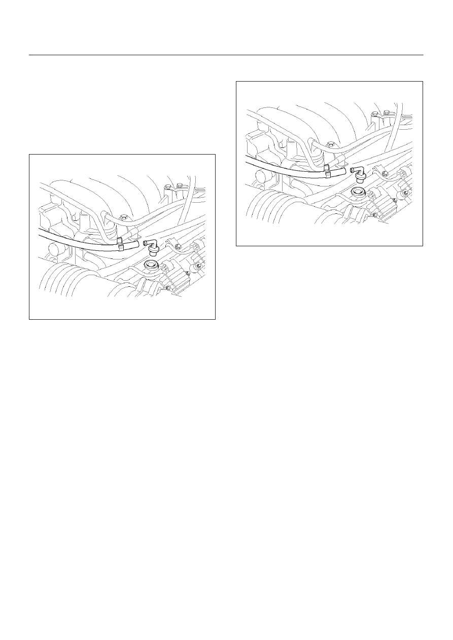
Removal Procedure
1. Remove the vacuum hose at the PCV valve.
D
Slide the clamp back to release the hose.
2. Pull the PCV valve from the rubber grommet in the
right valve cover.
014RW097
Inspection Procedure
Before inspecting the PCV valve, make sure that the
hoses are connected properly and are in good condition.
Also check that the oil pan and rocker cover gaskets are
sealing properly.
PCV Valve
1. Run the engine at normal operating temperature.
2. Disconnect the valve from the rocker cover.
RESULT: A hissing noise should be heard from the
valve. If no noise is heard, the PCV valve or hose is
plugged.
3. Remove the PCV valve from the engine.
a. Blow air into the rocker cover side of the valve.
RESULT: Air should pass freely.
b. Blow air into the air cleaner side of the valve.
RESULT: Air should not pass through the valve.
4. Re-install the PCV valve and remove the oil filler cap.
RESULT: A small vacuum should be felt at the oil filler
hole.
Installation Procedure
1. Push the PCV valve into the rubber grommet in the
left valve cover.
2. Install the vacuum hose on the PCV valve and secure
the vacuum hose with the clamp.
014RW097
Wiring and Connectors
Wiring Harness Service
The control module harness electrically connects the
control module to the various solenoids, switches and
sensors in the vehicle engine compartment and
passenger compartment.
Replace wire harnesses with the proper part number
replacement.
Because of the low amperage and voltage levels utilized
in powertrain control systems, it is essential that all wiring
in environmentally exposed areas be repaired with crimp
and seal splice sleeves.
The following wire harness repair information is intended
as a general guideline only. Refer to
Chassis Electrical
section for all wire harness repair procedures.
Connectors and Terminals
Use care when probing a connector and when replacing
terminals. It is possible to short between opposite
terminals. Damage to components could result. Always
use jumper wires between connectors for circuit
checking. NEVER probe through Weather-Pack seals.
Use an appropriate connector test adapter kit which
contains an assortment of flexible connectors used to
probe terminals during diagnosis. Use an appropriate
fuse remover and test tool for removing a fuse and to
adapt the fuse holder to a meter for diagnosis.
Open circuits are often difficult to locate by sight because
oxidation or terminal misalignment are hidden by the
connectors. Merely wiggling a connector on a sensor, or
in the wiring harness, may temporarily correct the open
circuit. Intermittent problems may also be caused by
oxidized or loose connections.
Be certain of the type of connector/terminal before
making any connector or terminal repair. Weather-Pack
and Com-Pack III terminals look similar, but are serviced
differently.