Isuzu Amigo / Axiom / Trooper / Rodeo / VehiCross. Manual - part 367


  Index      Isuzu     Isuzu Amigo / Axiom / Trooper / Rodeo / VehiCross - service repair manual 1999-2002 year


Search            


Content   ..  365  366  367  368   ..


Isuzu Amigo / Axiom / Trooper / Rodeo / VehiCross. Manual - part 367


6E–498

6VE1 3.5L ENGINE DRIVEABILITY AND EMISSIONS

Diagnostic Trouble Code (DTC) 

P1639 Reference Voltage # 2 Circuit Fault

060R200064

Circuit Description

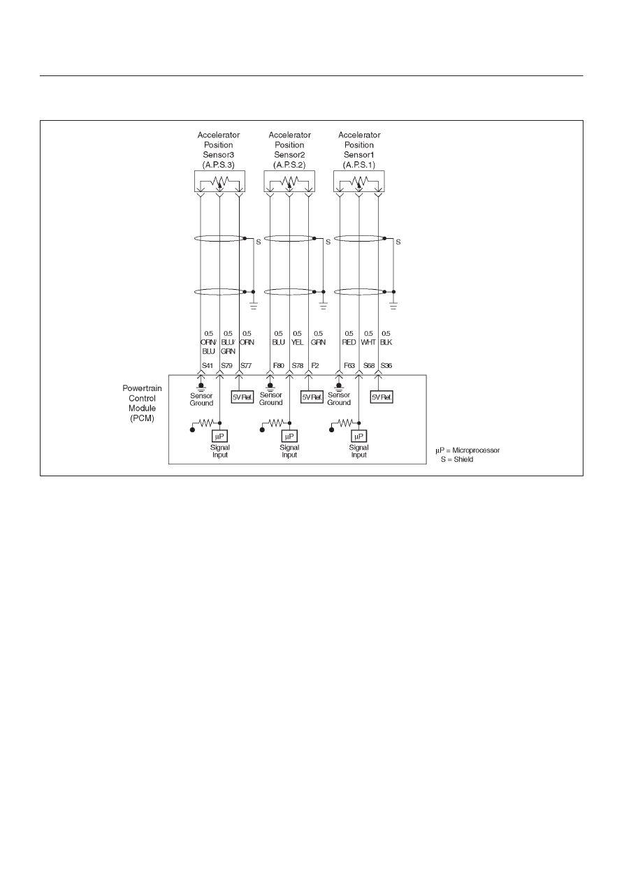
The AP sensor # 1shares a 5 Volt reference with the PCM.
If the PCM detects the 5 Volt reference for the AP sensor
# 1 is failure, DTC P1635 will be set.

Conditions for setting the DTC

D

The ignition is “ON”.

D

The 5 Volt reference voltage for the AP sensor # 1 is
less than 4 volts. 

D

The 5 Volt reference voltage for the AP sensor # 1 is
more than 5 volts.

Action Taken When the DTC Sets

D

The PCM will not illuminate the malfunction indicator
lamp (MIL).

D

The PCM will store conditions which were present
when the DTC was set as Failure Records only. This
information will not be stored as Freeze Frame data.

Conditions for Clearing the MIL/DTC

D

The PCM will turn the MIL “OFF” on the third
consecutive trip cycle during which the diagnostic has
been run and the fault condition is no longer present.

D

A history DTC P1639 will clear after 40 consecutive trip
cycles during which the warm up cycles have occurred
without a fault.

D

DTC P1639 can be cleared using the Tech 2 “Clear
Info” function or by disconnecting the PCM battery
feed. Tech 2 “Clear Info” function or by disconnecting
the PCM battery feed.

6E–499

6VE1 3.5L ENGINE DRIVEABILITY AND EMISSIONS

Diagnostic Trouble Code (DTC) 

P1639 Reference Voltage # 2 Circuit Fault


Step

Action

Value(s)

Yes

No

1

Was the “On-Board (OBD) System Check” performed?

Go to

 Step 2

Go to

 OBD

System

Check

2

1. Ignition “ON”, engine not running.
2. Using a DVM at the PCM side of the connector,

check the voltage at terminal S36 (BLK) pin.

Is the voltage in specified range?

4.95 – 5.0V

Go to

 ETC

System

Check

Go to

 Step 3 

3

1. Ignition “ON”, engine not running.
2. Using a DVM at the PCM side of the connector,

check the voltage at terminal F20(RED/WHT) pin.

Is the voltage in specified range?

11.6 – 12.7V

Go to

 Step 4 

Go to

 Step 5 

4

1. Ignition “ON”, engine not running.
2. Using a DVM at the PCM side of the connector,

check the voltage at terminal F57 (RED/WHT) pin.

Is the voltage in specified range?

11.6 – 12.7V

Go to

 Step 6 

Go to

 Step 5

5

Observe the battery voltage and circuit.
If a problem is found, repair it as necessary.

Was the problem found?

Verify repair

Go to

 Step 6 

6

Replace the PCM.

IMPORTANT:
The replacement PCM must be programmed. Refer to
ON-Vehicle Service in Power Control Module and
Sensors for procedures. 
And also refer to latest Service Bulletin. Check to see if
the latest software is released or not.
And then Down Load the LATEST PROGRAMMED
SOFTWARE to the replacement PCM.

Is the action complete?

Verify repair

6E–500

6VE1 3.5L ENGINE DRIVEABILITY AND EMISSIONS

Diagnostic Trouble Code (DTC) 

P1640 Driver-1-Output Circuit Fault (ODM)

Circuit Description

Output driver modules (ODMs) are used by the
powertrain control module (PCM) to turn “ON” many of
the current-driven devices that are needed to control
various engine and transmission functions.  Each ODM is
capable of controlling up to 7 separate outputs by
applying ground to the device which the PCM is
commanding “ON”.
Unlike the Quad Driver Modules (QDMs) used in prior
model years, ODMs have the capability of diagnosing
each output circuit individually.  DTC P1640 set indicates
an improper voltage level has been detected on an ODM
output.
Since A/C is an option, No A/C will cause the air
conditioning clutch relay output to always fail.  If a fault is
seen on the air conditioning clutch relay output, it will not
be logged as a fault until the A/C request input interrupts a
high voltage, indicating that A/C has been installed.

Conditions for Setting the DTC

D

Ignition “ON”.

D

Engine running.

D

Ignition voltage is above 13.2 volts for 4 seconds.

D

Output voltage does not equal ignition voltage when
output is “OFF” or output voltage is not less than 1 volt
when output is “ON”.

D

Above conditions occur for at least 1 second.

Action Taken When the DTC Sets

D

The PCM will not illuminate the malfunction indicator
lamp (MIL).

D

The PCM will store conditions which were present
when the DTC was set as Failure Records only.  This
information will not be stored as Freeze Frame data.

Conditions for Clearing the MIL/DTC

D

A history DTC P1640 will clear after 40 consecutive
warm-up cycles occur without a fault.

D

DTC P1640 can be cleared by using the Tech 2 “Clear
Info” function or by disconnecting the PCM battery
feed.

Diagnostic Aids

Check for the following conditions:

D

Poor connection at PCM – Inspect harness connectors
for backed-out terminals, improper mating, broken
locks, improperly formed or damaged terminals, and
poor terminal-to-wire connection.

D

Damaged harness – Inspect the wiring harness for
damage,  If the harness appears to be OK, disconnect
the PCM, turn the ignition “ON” and observe a
voltmeter connected to the suspect driver circuit at the
PCM harness connector while moving connectors and
wiring harnesses related to the MIL.  A change in
voltage will indicate the location of the fault.

D

Poor connection at component – Examine for
damaged connectors, unplugged connector, or
damaged terminals at the following locations:
Instrument cluster harness, canister purge solenoid,
A/C clutch relay.  An open ignition feed circuit at any of
these components will cause DTC P1640 to be set.

Reviewing the Failure Records vehicle mileage since the
diagnostic test last failed may help determine how often
the condition that caused the DTC to be set occurs.  This
may assist in diagnosing the condition.

Test Description

Number(s) below refer to the step number(s) on the
Diagnostic Chart.
4. The Tech 2 Driver Module Status indicates the PCM

pin that is affected.

9. The Tech 2 may indicate “short circuit” even when

the problem is an open circuit.  The cause of an
open circuit may be in the component itself-lamp,
purge, solenoid, or A/C compressor relay.

11.A short to ground on the ignition side of the

component will blow the fuse.  Since the fuse was
checked in Step 2, a short to ground would be
between the affected component and the PCM.

6E–501

6VE1 3.5L ENGINE DRIVEABILITY AND EMISSIONS

DTC P1640 – Driver-1-Output Circuit Fault (ODM)


Step

Action

Value(s)

Yes

No

1

Was the “On-Board Diagnostic (OBD) System Check”
performed?

Go to 

Step 2

Go to 

OBD

System

Check

2

Check the fuse for the driver circuit that was shown as
faulty.

Was the fuse blown?

Go to 

Step 3

Go to 

Step 4

3

1. Check for a short to ground between the fuse and

the affected component.

2. Replace the fuse after making any necessary

repairs.

Is the action complete?

Verify repair

4

Disconnect the PCM connector for the affected driver
circuit.

Is there any damage to the PCM pin or connector?

Go to 

Step 5

Go to 

Step 6

5

Repair the damaged pin or terminal.

Is the action complete?

Verify repair

6

Were either of the lamp circuits for “Check Engine” or
“Check Trans” indicated as faulty by the Tech 2?

Go to 

Step 7

Go to 

Step 13

7

1. Leave the PCM connector for the lamp driver circuit

disconnected.

2. Ignition “ON”.
3. Using a DVM, check the voltage at the PCM

connector  for the affected lamp driver circuit.

Was the voltage equal to the specified value?

B+

Go to 

Step 15

Go to 

Step 8

8

1. Ignition “ON”.
2. Check for battery voltage at the fuse for the affected

lamp circuit.

Was battery voltage available at the fuse?

Go to 

Step 10

Go to 

Step 9

9

Repair the open circuit between the ignition switch and
the fuse.

Is the action complete?

Verify repair

10

1. Ignition “OFF”.
2. Disconnect the PCM connector for the affected

driver terminal.

3. Connect an ohmmeter between a good ground and

the PCM connector for the affected driver.

Did the ohmmeter indicate continuity?

Go to 

Step 11

Go to 

Step 12

11

Repair the short to ground between the affected
component and its PCM driver terminal.

Is the action complete?

Verify repair

12

Repair the open circuit between the fuse and the PCM
driver terminal for the affected circuit.

Is the action complete?

Verify repair


Content   ..  365  366  367  368   ..