Isuzu Amigo / Axiom / Trooper / Rodeo / VehiCross. Manual - part 276


  Index      Isuzu     Isuzu Amigo / Axiom / Trooper / Rodeo / VehiCross - service repair manual 1999-2002 year


Search            


Content   ..  274  275  276  277   ..


Isuzu Amigo / Axiom / Trooper / Rodeo / VehiCross. Manual - part 276


6E–134

6VE1 3.5L ENGINE DRIVEABILITY AND EMISSIONS

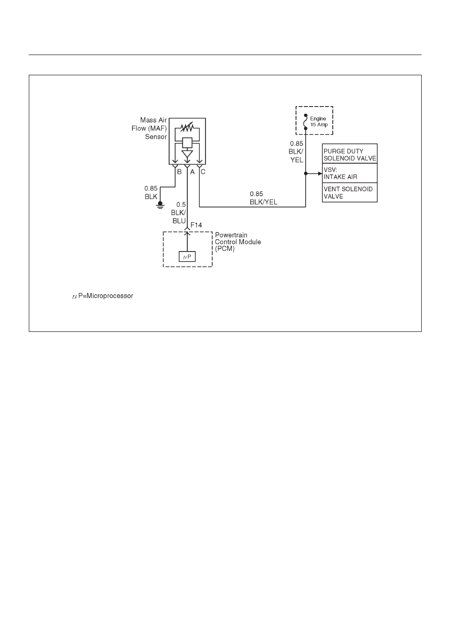
Diagnostic Trouble Code (DTC) P0102 MAF Sensor Circuit  Low Frequency

060R200052

Circuit Description

The mass air flow (MAF) sensor measures the amount of
air which passes through it into the engine during a given
time.  The powertrain control module (PCM) uses the
mass air flow information to monitor engine operating
conditions for fuel delivery calculations.  A large quantity
of air entering the engine indicates an acceleration or high
load situation, while a small quantity of air indicates
deceleration or idle.
The MAF sensor produces a frequency signal which can
be monitored using a Tech 2.  The frequency will vary
within a range of around 4 to 7g/s at idle to around 25 to 40
g/s at maximum engine load.  DTC P0102 will be set if the
signal from the MAF sensor is below the possible range of
a normally operating MAF sensor.

Conditions for Setting the DTC

D

The engine is running above 500 RPM for more than
10 seconds.

D

System voltage is above 11.5 volts.

D

MAF signal frequency is below 1.6g/s for a total of
50-percent of the last 1000 samples monitored.  A
sample is taken every cylinder event.

Action Taken When the DTC Sets

D

The PCM will ON the MIL after second trip with
detected fault.

D

The PCM calculates an air flow value based on idle air
control valve position, throttle position, RPM and
barometric pressure.

D

The PCM will store conditions which were present
when the DTC was set as Freeze Frame and in the
Failure Records data.

Conditions for Clearing the MIL/DTC

D

The PCM will turn the MIL “OFF” on the third
consecutive trip cycle during which the diagnostic has
been run and the fault condition is no longer present.

D

A history DTC P0102 will clear after 40 consecutive
warm-up cycles have occurred without a fault.

D

DTC P0102 can be cleared by using the Tech 2 “Clear
Info” function or by disconnecting the PCM battery
feed.

Diagnostic Aids

Check for the following conditions:

D

Poor connection at PCM – Inspect harness connectors
for backed-out terminals, improper mating, broken
locks, improperly formed or damaged terminals, and
poor terminal-to-wire connection.

D

Misrouted harness – Inspect the MAF sensor harness
to ensure that it is not routed too close to high voltage
wires.

D

Damaged harness – Inspect the wiring harness for
damage.  If the harness appears to be OK, observe the
Tech 2 while moving connectors and wiring harnesses
related to the MAF sensor.  A change in the display will
indicate the location of the fault.

D

Plugged intake air duct or filter element – A wide-open
throttle acceleration from a stop should cause the
mass air flow displayed on a Tech 2 to increase from

6E–135

6VE1 3.5L ENGINE DRIVEABILITY AND EMISSIONS

about 3-6 g/second at idle to 100 g/second or greater
at the time of the 1-2 shift.  If not, check for a restriction.

If DTC P0102 cannot be duplicated, the information
included in the Failure Records data can be useful in
determining vehicle mileage since the DTC was last set.

Test Description

Number(s) below refer to the step number(s) on the
Diagnostic Chart.

2. This step verifies that the problem is present at idle.

4. A voltage reading of less than 4 or over 5 volts at the

MAF sensor signal circuit indicates a fault in the
wiring or a poor connection.

5. This verifies that ignition feed voltage and a good

ground are available at the MAF sensor.

DTC P0102 – MAF Sensor Circuit Low Frequency


Step

Action

Value(s)

Yes

No

1

Was the “On-Board Diagnostic (OBD) System Check”
performed?

Go to 

Step 2

Go to 

OBD

System

Check

2

1. Start the engine.
2. With the engine idling, monitor “MAF Frequency”

display on the Tech 2.

Is the “MAF Frequency” below the specified value?

1.6 g/s

Go to 

Step 3

Go to 

Step 5

3

1. Ignition “ON”, engine “OFF”.
2. Review and record Tech 2 Failure Records data.
3. Operate the vehicle within Failure Records

conditions as noted.

4. Using a Tech 2, monitor “DTC” info for DTC P0102.

Does the Tech 2 indicate DTC P0102 failed this
ignition?

Go to 

Step 4

Refer to

Diagnostic

Aids

4

1. Ignition “OFF”.
2. Disconnect the MAF sensor connector.
3. Ignition “ON”, engine “OFF”.
4. Using a DVM, measure voltage between the MAF

sensor signal circuit and battery ground.

Is the voltage near the specified value?

11.5–12 V

Go to 

Step 5

Go to 

Step 8

5

Connect a test light between the MAF sensor ignition
feed and ground circuits at the MAF sensor harness
connector.

Is the test light “ON”?

Go to 

Step 7

Go to 

Step 6

6

Connect a test light between the MAF sensor ignition
feed circuit and battery ground.

Is the test light “ON”?

Go to 

Step 11

Go to 

Step 7

7

1. Check for a poor connection at the MAF sensor.
2. If a poor connection is found, replace the faulty

terminal(s).

Was a poor connection found?

Verify repair

Go to 

Step 12

8

1. Ignition “OFF”.
2. Disconnect the MAF sensor.
3. Disconnect the PCM connector for the MAF signal

circuit.

4. Ignition “ON”, engine “OFF”.
5. With the DVM, measure the voltage between the

MAF signal terminal at the PCM and battery ground.

Is the voltage under the specified value?

0 V

Go to 

Step 9

Go to 

Step 10

6E–136

6VE1 3.5L ENGINE DRIVEABILITY AND EMISSIONS

DTC P0102 – MAF Sensor Circuit Low Frequency

  (Cont'd)

Step

No

Yes

Value(s)

Action

9

1. Ignition “OFF”.
2. Disconnect the PCM connector.
3. Ignition “ON”.
4. Check the MAF sensor signal circuit for a short to 5

volts.

Is the action complete?

Verify repair

10

1. Ignition “OFF”.
2. Disconnect the PCM connector.
3. Ignition “ON”.
4. Check the MAF sensor signal circuit between the

PCM and the MAF sensor for an open, short to
ground, or short to the MAF ground circuit.

Is the action complete?

Verify repair

Go to 

Step 13

11

Locate and repair the open in the ground circuit to the
MAF sensor.

Is the action complete?

Verify repair

12

Locate and repair the open in the ignition feed circuit to
the MAF sensor.

Is the action complete?

Verify repair

13

Replace the MAF sensor.

Is the action complete?

Verify repair

Go to 

Step 14

14

Replace the PCM.

IMPORTANT: The replacement PCM must be
programmed.  Refer to 

On-Vehicle Service in

Powertrain Control Module and Sensors for
procedures.

And also refer to latest Service Bulletin.

Check to see if the Latest software is released or not.
And then Down Load the LATEST PROGRAMMED
SOFTWARE to the replacement PCM.

Is the action complete?

Verify repair

6E–137

6VE1 3.5L ENGINE DRIVEABILITY AND EMISSIONS

Diagnostic Trouble Code (DTC) P0103 MAF Sensor Circuit High Frequency

060R200052

Circuit Description

The mass air flow (MAF) sensor measures the amount of
air which passes through it into the engine during a given
time.  The powertrain control module (PCM) uses the
mass air flow information to monitor engine operating
conditions for fuel delivery calculations.  A large quantity
of air entering the engine indicates an acceleration or high
load situation, while a small quantity of air indicates
deceleration or idle.
The MAF sensor produces a frequency signal which can
be monitored using a Tech 2.  The frequency will vary
within a range of around 4 to 7g/s at idle to around 25 to 40
g/s at maximum engine load.  DTC P0103 will be set if the
signal from the MAF sensor is above the possible range of
a normally operating MAF sensor.

Conditions for Setting the DTC

D

The engine is running above 500 RPM for more than
10 seconds.

D

System voltage is above 11.5 volts.

D

MAF signal frequency is above 40g/s for a total of 50
percent of the last 200 samples monitored.  A sample
is taken every cylinder event.

Action Taken When the DTC Sets

D

The PCM will ON the MIL after second trip with
detected the fault.

D

The PCM calculates an airflow value based on idle air
control valve position, throttle position, RPM and
barometric pressure.

D

The PCM will store conditions which were present
when the DTC was set as Freeze Frame and in the
Failure Records data.

Conditions for clearing the MIL/DTC

D

The PCM will turn the MIL “OFF” on the third
consecutive trip cycle during which the diagnostic has
been run and the fault condition is no longer present.

D

A history DTC P0103 will clear after 40 consecutive
warm-up cycles have occurred without a fault.

D

DTC P0103 can be cleared by using the Tech 2 “Clear
Info” function or by disconnecting the PCM battery
feed.

Diagnostic Aids

If DTC P0103 cannot be duplicated, the information
included in the Failure Records data can be useful in
determining vehicle mileage since the DTC was last set.

Test Description

Number(s) below refer to the step number(s) on the
Diagnostic Chart.
2. This step verifies that the problem is present at idle.


Content   ..  274  275  276  277   ..