Isuzu Amigo / Axiom / Trooper / Rodeo / VehiCross. Manual - part 202


  Index      Isuzu     Isuzu Amigo / Axiom / Trooper / Rodeo / VehiCross - service repair manual 1999-2002 year


Search            


Content   ..  200  201  202  203   ..


Isuzu Amigo / Axiom / Trooper / Rodeo / VehiCross. Manual - part 202


5D1–7

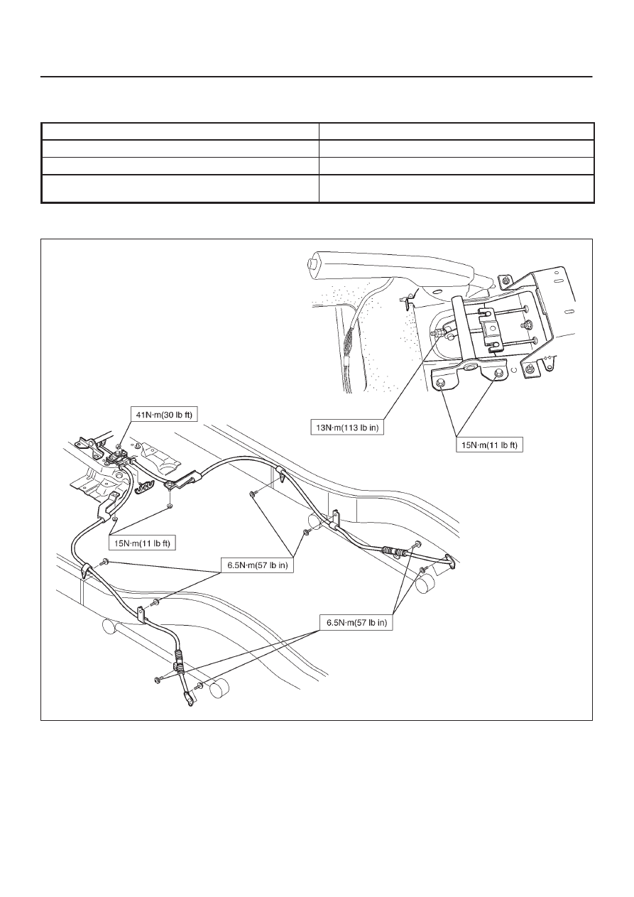
PARKING BRAKE SYSTEM (4x4 Model)

Main Data and Specifications

General Specifications

Model

Type

Duo–servo

Drum inside diameter

210 mm(8.27 in)

Parking brake lever stroke

6–8 notches

When pulled with a force of 30 kg (66 lb)

Torque Specifications

311R200002

PARKING BRAKE SYSTEM (4X2 Model) 5D2–1

AXIOM

BRAKES

PARKING BRAKE SYSTEM (4

×

2 Model)

CONTENTS

Service Precaution

5D2–1

. . . . . . . . . . . . . . . . . . . . . . 

General Description

5D2–1

. . . . . . . . . . . . . . . . . . . . . 

Parking Brake Lever

5D2–2

. . . . . . . . . . . . . . . . . . . . . 

Parking Brake Lever Assembly and
 Associated Parts

5D2–2

. . . . . . . . . . . . . . . . . . . . . . 

Removal

5D2–2

. . . . . . . . . . . . . . . . . . . . . . . . . . . . . 

Installation

5D2–2

. . . . . . . . . . . . . . . . . . . . . . . . . . . . 

Parking Brake Rear Cable

5D2–3

. . . . . . . . . . . . . . . . 

Parking Brake Rear Cable and Associated
 Parts

5D2–3

. . . . . . . . . . . . . . . . . . . . . . . . . . . . . . . . 

Removal

5D2–4

. . . . . . . . . . . . . . . . . . . . . . . . . . . . . 

Installation

5D2–4

. . . . . . . . . . . . . . . . . . . . . . . . . . . . 

Parking Brake Adjustment

5D2–4

. . . . . . . . . . . . . . . . 

Main Data and Specifications

5D2–5

. . . . . . . . . . . . . 

Service Precaution

WARNING: THIS VEHICLE HAS A SUPPLEMENTAL
RESTRAINT SYSTEM (SRS). REFER TO THE SRS
COMPONENT AND WIRING LOCATION VIEW IN
ORDER TO DETERMINE WHETHER YOU ARE
PERFORMING SERVICE ON OR NEAR THE SRS
COMPONENTS OR THE SRS WIRING. WHEN YOU
ARE PERFORMING SERVICE ON OR NEAR THE SRS
COMPONENTS OR THE SRS WIRING, REFER TO
THE SRS SERVICE INFORMATION. FAILURE TO
FOLLOW WARNINGS COULD RESULT IN POSSIBLE
AIR BAG DEPLOYMENT, PERSONAL INJURY, OR
OTHERWISE UNNEEDED SRS SYSTEM REPAIRS.

CAUTION: Always use the correct fastener in the
proper location. When you replace a fastener, use
ONLY the exact part number for that application.
ISUZU will call out those fasteners that require a
replacement after removal. ISUZU will also call out
the fasteners that require thread lockers or thread
sealant. UNLESS OTHERWISE SPECIFIED, do not
use supplemental coatings (Paints, greases, or other
corrosion inhibitors) on threaded fasteners or
fastener joint interfaces. Generally, such coatings
adversely affect the fastener torque and the joint
clamping force, and may damage the fastener. When
you install fasteners, use the correct tightening
sequence and specifications. Following these
instructions can help you avoid damage to parts and
systems.

General Description

Pulling up the parking brake lever by hand will set the
parking brake. By means of a ratchet type lock, the lever
can be held in that position until it is released. The position
of the lever is transmitted through cable/lever systems to
the rear wheels. These parts are designed to obtain
sufficient braking force even when parking on slopes.
When the parking brake is set, or when the ignition SW is
in the“ON” position, the brake warning light illuminates.
The rear wheel parking brake is a leading/trailing brake
(mechanical inside expansion type). Parking brake
adjustment is made through the adjusting hole (bored
through back plate). Parking brake lever stroke should be
adjusted to 6 notches. Refer to 

Parking Brake Adjustment

in this section.

SECTION

5D2–2

PARKING BRAKE SYSTEM (4X2 Model)

Parking Brake Lever

Parking Brake Lever Assembly and Associated Parts

311R200001

Legend

(1) Rear Console
(2) Switch Connector
(3) Bolt
(4) Adjust Nut and Lock Nut

(5) Trunnion Pin
(6) Equalizer
(7) Parking Brake Rear Cable
(8) Parking Brake Lever

Removal

1. Remove rear console (1).

D

Refer to 

Body and Accessories section in this

manual.

2. Disconnect switch connector (2).
3. Remove bolt (3).
4. Remove adjust nut and lock nut (4).
5. Pull out equalizer (6) from trunnion pin (5).
6. Disconnect trunnion pin (5) from parking brake lever

(8).

7. Disconnect parking brake rear cable (7).

Installation

1. Apply grease (BESCO L–2 or equivalent) to the

connecting portion of the rear cable (7) and equalizer
(8).

2. Connect parking brake rear cable (7) to equalizer (6).
3. Install trunnion pin (5) to parking brake lever (8).
4. Insert equalizer (6) into trunnion pin (5) and tighten

adjust nut and lock nut (4).

D

To adjust the parking brake lever, see “Parking
Brake Adjustment” in this section.

Lock Nut Torque: 13 N·m (113 lb in)

5. Tighten parking lever fixing bolt (3) to the specified

torque.

Torque: 15 N·m (11 lb ft)

6. Connect switch connector (2).
7. Install rear console (1).

D

Refer to 

Body and Accessories section in this

manual.

PARKING BRAKE SYSTEM (4X2 Model) 5D2–3

Parking Brake Rear Cable

Parking Brake Rear Cable and Associated Parts

311RY00006

Legend

(1) Rear Wheels
(2) Drums
(3) Clip and Bolt
(4) Clip and Bolt

(5) Clip and Bolt (Only Long Wheel Base Model)
(6) Nut
(7) Nut
(8) Retainer
(9) Rear Cable


Content   ..  200  201  202  203   ..