Isuzu Amigo / Axiom / Trooper / Rodeo / VehiCross. Manual - part 200


  Index      Isuzu     Isuzu Amigo / Axiom / Trooper / Rodeo / VehiCross - service repair manual 1999-2002 year


Search            


Content   ..  198  199  200  201   ..


Isuzu Amigo / Axiom / Trooper / Rodeo / VehiCross. Manual - part 200


5C–117

POWER–ASSISTED BRAKE SYSTEM

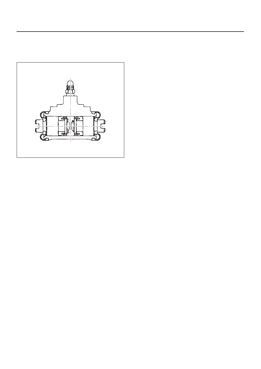
3. Install new piston cups (3) on each piston so that the

flared end of the cups are turned to the inboard side of
the pistons.
Attach the return spring (4) and the boot (1) to the
piston.

305RS009

4. Apply DELCO silicone lube No. 5459912 (or

equivalent) to the piston and the inner face of the
boots.

5. Install piston assembly (2) to wheel cylinder (6).

5C–118 POWER–ASSISTED BRAKE SYSTEM

Main Data and Specifications

General Specifications

Rear drum brake

Type

Leading-trailing, non-servo

Drum inside diameter

295 mm (11.6 in)

Wheel cylinder diameter

22.22 mm (7/8 in)

Torque Specifications

E05RW010

5D1–1

PARKING BRAKE SYSTEM (4x4 Model)

AXIOM

BRAKES

PARKING BRAKE SYSTEM (4

×

4 Model)

CONTENTS

Service Precaution

5D1–1

. . . . . . . . . . . . . . . . . . . . . . 

General Description

5D1–1

. . . . . . . . . . . . . . . . . . . . . 

Operation

5D1–2

. . . . . . . . . . . . . . . . . . . . . . . . . . . . . . 

Parking Brake Lever and Front Cable

5D1–3

. . . . . . 

Parking Brake Lever Assembly and
 Associated Parts

5D1–3

. . . . . . . . . . . . . . . . . . . . . . 

Removal

5D1–3

. . . . . . . . . . . . . . . . . . . . . . . . . . . . . 

Installation

5D1–3

. . . . . . . . . . . . . . . . . . . . . . . . . . . . 

Parking Brake Rear Cable

5D1–4

. . . . . . . . . . . . . . . . 

Parking Brake Rear Cable and Associated
 Parts

5D1–4

. . . . . . . . . . . . . . . . . . . . . . . . . . . . . . . . 

Removal

5D1–5

. . . . . . . . . . . . . . . . . . . . . . . . . . . . . 

Installation

5D1–5

. . . . . . . . . . . . . . . . . . . . . . . . . . . . 

Inspection and Repair

5D1–6

. . . . . . . . . . . . . . . . . . 

Parking Brake Adjustment

5D1–6

. . . . . . . . . . . . . . . . 

Main Data and Specifications

5D1–7

. . . . . . . . . . . . . 

Service Precaution

WARNING: THIS VEHICLE HAS A SUPPLEMENTAL
RESTRAINT SYSTEM (SRS). REFER TO THE SRS
COMPONENT AND WIRING LOCATION VIEW IN
ORDER TO DETERMINE WHETHER YOU ARE
PERFORMING SERVICE ON OR NEAR THE SRS
COMPONENTS OR THE SRS WIRING. WHEN YOU
ARE PERFORMING SERVICE ON OR NEAR THE SRS
COMPONENTS OR THE SRS WIRING, REFER TO
THE SRS SERVICE INFORMATION. FAILURE TO
FOLLOW WARNINGS COULD RESULT IN POSSIBLE
AIR BAG DEPLOYMENT, PERSONAL INJURY, OR
OTHERWISE UNNEEDED SRS SYSTEM REPAIRS.

CAUTION: Always use the correct fastener in the
proper location. When you replace a fastener, use
ONLY the exact part number for that application.
ISUZU will call out those fasteners that require a
replacement after removal. ISUZU will also call out
the fasteners that require thread lockers or thread
sealant. UNLESS OTHERWISE SPECIFIED, do not
use supplemental coatings (Paints, greases, or other
corrosion inhibitors) on threaded fasteners or
fasteners joint interfaces. Generally, such coatings
adversely affect the fastener torque and the joint
clamping force, and may damage the fasteners.
When you install fasteners, use the correct
tightening sequence and specifications. Following
these instructions can help you avoid damage to
parts and systems.

General Description

Pulling up the parking brake lever by hand will set the
parking brake. By means of a ratchet type lock, the lever
can be held in that position until it is released. The position
of the lever is transmitted through cable/lever systems to
the rear wheels. These parts are designed to obtain
sufficient braking force even when parking on slopes.
When the parking brake is set, or when the ignition SW is
in the“ON” position, the brake warning light illuminates.
The rear wheel parking brake is a duo–servo brake
(mechanical inside expansion type) built in the rear disc
brake. Parking brake adjustment is made through the
adjusting hole (bored through back plate). Parking brake
lever stroke should be adjusted to 6–8 notches. Refer to
Parking Brake Adjustment in this section.

SECTION

5D1–2 PARKING BRAKE SYSTEM (4x4 Model)

Operation

When pulled in the direction “A”, the parking lever presses
the secondary shoe against the brake drum using the
lever/shoe joint “B” as a fulcrum and pushes the strut in
the direction “C”. The strut ,in turn, presses the primary
shoe against the brake drum. Counter force “D” to the
primary shoe is transmitted again to the secondary shoe
through the fulcrum “B”. The secondary shoe contacts the
drum thereby producing braking effect. Clearance which
may result from worn parking brake shoe lining can be
adjusted by turning the adjusting screw. Refer to 

Parking

Brake Adjustment in this Section.

A05RS002

Legend

(1) Direction “A”
(2) Lever/Shoe Joint “B” as a fulcrum
(3) Direction “C”
(4) Counter Force “D”
(5) Parking Lever
(6) Secondary Shoe
(7) Adjusting Screw Notch

(8) Parking Cable Guide
(9) Primary Shoe

(10) Strut

(11) Shoe Expanding Direction

(12) Parking Brake Cable Guide
(13) Adjusting Hole Plug
(14) Adjusting Screw Notch


Content   ..  198  199  200  201   ..