Isuzu Amigo / Axiom / Trooper / Rodeo / VehiCross. Manual - part 197


  Index      Isuzu     Isuzu Amigo / Axiom / Trooper / Rodeo / VehiCross - service repair manual 1999-2002 year


Search            


Content   ..  195  196  197  198   ..


Isuzu Amigo / Axiom / Trooper / Rodeo / VehiCross. Manual - part 197


5C–105

POWER–ASSISTED BRAKE SYSTEM

Minimum wear dimension: 16.6 mm (0.654 in)

Refinish dimension: 16.97 mm (0.668 in)

420RW002

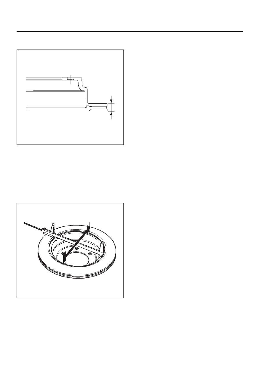
Rear Drum (In Disc) Inside Diameter
Check

Check the rear drum inside diameter by measuring at
more than two portions as shown in the illustration.
If the inside diameter is greater than the limit, replace the
rear rotor.

Standard: 210.0 mm (8.27 in)

Limit: 211.4 mm (8.32 in)

420RS035

5C–106POWER–ASSISTED BRAKE SYSTEM

Rear Disc Brake Caliper Assembly (4

×

4 Model)

Rear Disc Brake Caliper Assembly and Associated Parts

306RW007

Legend

(1) Brake Flexible Hose
(2) Clip
(3) Lock Bolt

(4) Support Bracket
(5) Guide Bolt
(6) Pad Assembly with Shim
(7) Caliper Assembly

Removal

1. Raise the vehicle and support with suitable safety

stands.

2. Remove wheel and tire assembly, referring to 

Wheels

and Tires System in Section 3E.

3. Remove the bolt and gaskets, then disconnect the

flexible hose from the caliper and after disconnecting
the flexible hose (1), cap or tape the openings to
prevent entry of foreign material.

306RW008

4. Since the brake fluid flows out from the connecting

coupler, place a drain pan under the vehicle.

5. Remove lock bolt (3).
6. Remove guide bolt (2).

306RW009

7. Remove caliper assembly.
8. Remove support bracket with pad assembly and take

care not to damage the flexible brake hose when
removing the support bracket.

9. Remove pad assembly with shim and mark the lining

locations if they are to be reinstalled.

5C–107

POWER–ASSISTED BRAKE SYSTEM

10. Remove clip.

Installation

1. Install clip (4).

306RW010

2. Apply special grease (approximately 0.2 g) to both

contacting surfaces of the inner shims (5). Wipe off
extruded grease after installing. Install pad assembly
with shim.

306RW011

Legend

(5) Inner Shim
(6) Wear indicator

3. Install support bracket and tighten the bolt (7) to the

specified torque.

Torque: 103 N·m (76 lb ft)

306RW012

4. Install caliper assembly.
5. Install lock bolt and guide bolt (8) and tighten the bolt

to the specified torque.

Torque: 44 N·m (32 lb ft)

306R200004

6. Install brake flexible hose, always use new gaskets

and be sure to put the hooked edge of the flexible
hose end into the anti–rotation cavity then tighten the
eye–bolt (9) to the specified torque.

Torque: 35 N·m (26 lb ft)

5C–108POWER–ASSISTED BRAKE SYSTEM

302RW017

7. Install the wheel and tire assembly, referring to

Wheels and Tires System in Section 3E.

8. Bleed brakes. Refer to 

Hydraulic Brakes in this

section.

Rear Disc Brake Caliper (4

×

4 Model)

Rear Disc Brake Caliper Disassembled View

306RW014

Legend

(1) Guide Bolt
(2) Lock Bolt
(3) Bleeder with Cap
(4) Caliper Body

(5) Piston Seal
(6) Piston
(7) Dust Boot: Piston
(8) Dust Boot Ring
(9) Dust Boot: Guide Bolt and Lock Bolt


Content   ..  195  196  197  198   ..