Isuzu Amigo / Axiom / Trooper / Rodeo / VehiCross. Manual - part 175


  Index      Isuzu     Isuzu Amigo / Axiom / Trooper / Rodeo / VehiCross - service repair manual 1999-2002 year


Search            


Content   ..  173  174  175  176   ..


Isuzu Amigo / Axiom / Trooper / Rodeo / VehiCross. Manual - part 175


5C–17

POWER–ASSISTED BRAKE SYSTEM

Brake Pedal

Checking Pedal Height

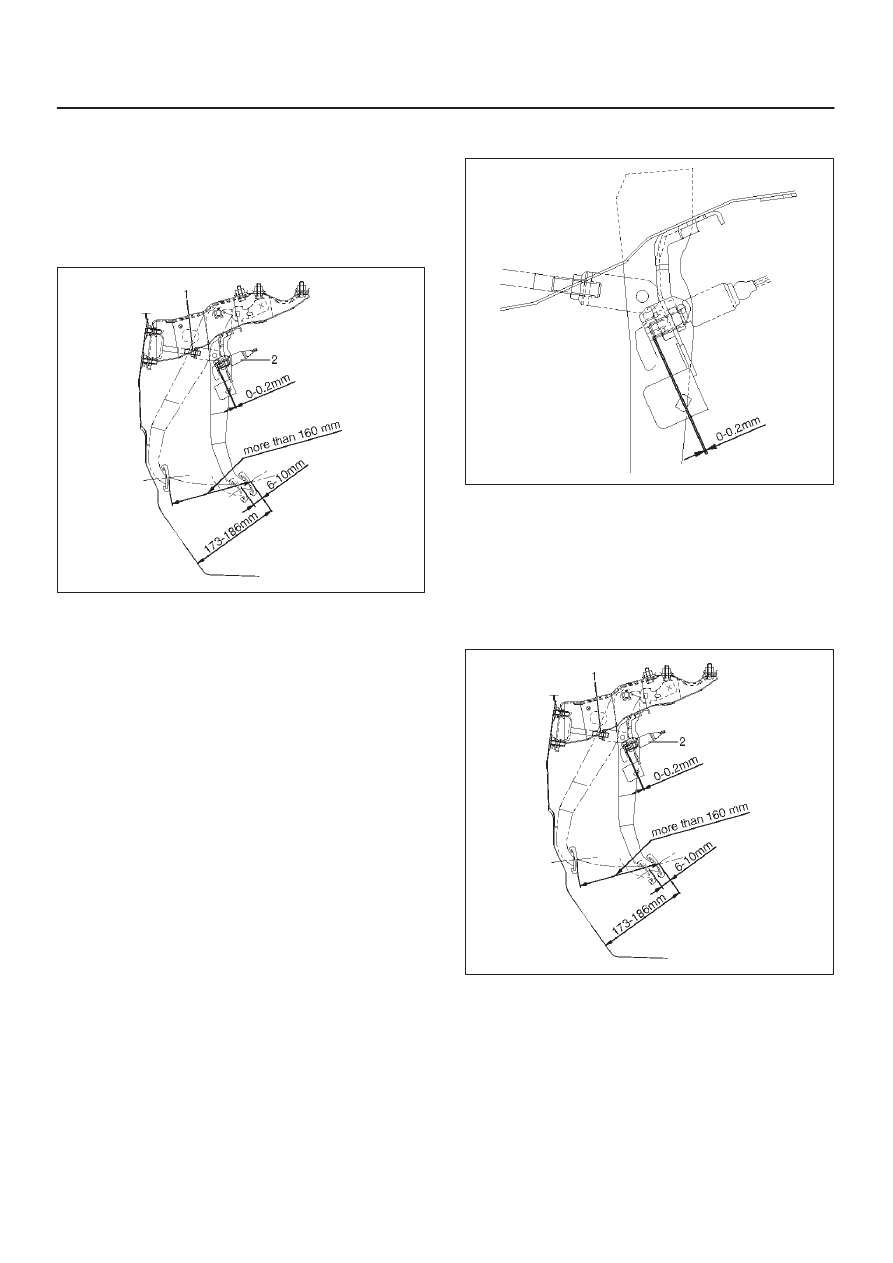
The push rod serves as the brake pedal stopper when the
pedal is fully released. Brake pedal height adjustment
should be performed as follows:

Adjust Brake Pedal

310RY00004

1. Measure the brake pedal height after making sure the

pedal is fully returned by the pedal return spring.
Pedal height must be measured after starting the
engine and receiving it several times.

Pedal Free Play: 6-10 mm (0.23-0.39 in)

Pedal Free Play: 173-185 mm (6.81-7.28 in)

NOTE: Pedal free play must be measured after turning
off the engine and stepping on the brake pedal firmly five
times or more.

2. If the measured value is not within the above range,

adjust the brake pedal as follows:
a. Disconnect the stoplight switch connector.
b. Loosen the stoplight switch lock nut.
c. Rotate the stoplight switch so that it moves away

from the brake pedal.

d. Loosen the lock nut (1) on the push rod.
e. Adjust the brake pedal to the specified height by

rotating the push rod in the appropriate direction.

f. Tighten the lock nut to the specified torque.

Torque: 20 N·m (15 lb ft)

g. Adjust the stoplight switch (2) to the specified

clearance (between the switch housing and the
brake pedal) by rotating the switch housing.

Clearance: 0.5–1.0 mm (0.02–0.04 in)

310RY00005

NOTE: While adjusting the stoplight switch, make sure
that the threaded part of the stoplight switch does not
push the brake pedal.

h. Tighten the stoplight switch lock nut.
i. Connect the stoplight switch connector.

Checking Pedal Travel

310RY00004

1. Pedal height must be measured after starting the

engine and revving it several times to apply vacuum
to the vacuum booster fully.

NOTE: Pedal height must be 95 mm (3.7 in) or more
when about 50 kg (110.25 lb) of stepping force is applied.

2. If the measured value is lower than the above range,

air may still be present in the hydraulic system
Perform the bleeding procedure.

5C–18 POWER–ASSISTED BRAKE SYSTEM

Brake Pedal and Associated Parts

310RY00006

Legend

(1) Brake Pedal Bracket Assembly
(2) Fulcrum Pin and Nut
(3) Connector
(4) Snap Pin
(5) Return Spring

(6) Peadl Assembly
(7) Push Rod Pin
(8) Lower Cover
(9) Bolts and Nut

(10) Driver Knee Bolster

Removal

1. Disconnect the battery “–” terminal cable, and wait at

least 5 minutes.

2. Disconnect the yellow 3 way SRS connector located

under the steering column.

3. Remove the engine hood opening lever.
4. Remove lower cover (8).
5. Remove driver knee bolster (10).
6. Disconnect the stop light switch connector (3).

Disconnect the anti-theft control module connector.
Refer to 

Body and Accessories section in this

Manual.

7. Remove snap pin (4) and push rod pin (7).
8. Remove the steering column shaft fixing bolt and nut

(9) on the steering wheel side, and lower the steering
column shaft.

9. Remove the brake pedal bracket assembly (1).

10. Remove return spring (5).

11. Remove fulcrum pin and nut (2).

12. Remove pedal assembly (6).

Installation

1. Apply grease to the entire circumference of the

fulcrum pin.

2. Install pedal assembly (6) and fulcrum pin and nut (2).

Tighten the nut (2) to the specified torque.

Torque: 35 N·m (26 lb ft)

3. Install the brake pedal bracket assembly (1).

Tighten the bolts and nuts soecified torque.

Torque: 15 N·m (11 lb ft)

4. Install return spring (5).
5. Adjust pedal free travel.

Refer to 

Brake Pedal Adjustment in this section.

6. Tighten the steering column fixing bolt (9) (dash

panel) to the specified torque.

Torque: 20 N·m (14 lb ft)

5C–19

POWER–ASSISTED BRAKE SYSTEM

7. Tighten the steering column fixing nut (9) (Cross

Beam) to the specified torque.

Torque: 17 N·m (12 lb ft)

8. Apply grease to the entire circumference of the Push

rod pin (7).

9. Install push rod pin (7).

10. Install snap pin (4).

11. Connect the anti-theft control module connector.

Refer to 

Body and Accessories section in this

manual.

12. Connect the stop light switch connector (3).
13. Install driver knee bolster (10) and lower cover (8).
14. Install the engine hood opening lever.
15. Connect the yellow 3 way SRS connector located

under the steering column.

16. Connect the battery “–” terminal cable.

Stoplight Switch

Parts Location

310RW008

Legend

(1) Connector
(2) Switch
(3) Lock Nut

Removal

1. Disconnect connector (1)
2. Remove lock nut (3).
3. Remove switch (2).

Installation

1. Adjust the stop light switch to the specified clearance

(between switch housing and brake pedal) by rotating
the switch housing.

Clearance : 0-0.2 mm (0-0.08 in)

NOTE: Do not attempt to force the push rod into position
during the stop light switch installation and adjustment
procedure.

310RY00005

2. Connect connector (1).
3. Install lock nut (3).

5C–20 POWER–ASSISTED BRAKE SYSTEM

Main Data and Specifications

General Specifications

Pedal free play

6–10 mm (0.23 –0.39 in)

Pedal Height

173–185 mm (6.81–7.28 in)

Torque Specifications

310RY00007


Content   ..  173  174  175  176   ..