Isuzu Amigo / Axiom / Trooper / Rodeo / VehiCross. Manual - part 174


  Index      Isuzu     Isuzu Amigo / Axiom / Trooper / Rodeo / VehiCross - service repair manual 1999-2002 year


Search            


Content   ..  172  173  174  175   ..


Isuzu Amigo / Axiom / Trooper / Rodeo / VehiCross. Manual - part 174


5C–13

POWER–ASSISTED BRAKE SYSTEM

Rear Axle Brake Hose

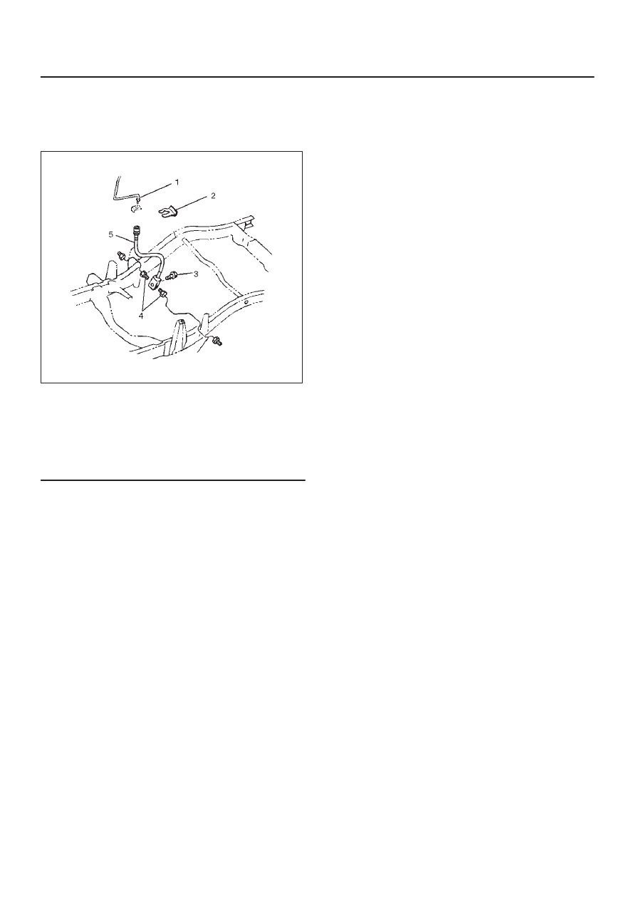
Rear Axle Brake Hose and Associated
Parts

352RW002

Legend

(1) Brake Pipe
(2) Clip
(3) Bolt
(4) Brake Pipe
(5) Hose

Removal

1. Raise the vehicle and support it with suitable safety

stands.

2. Remove wheel and tire assembly.
3. Clean dirt, grease, and other foreign material off the

hose fittings at both ends.

4. Disconnect brake pipe.
5. Remove clip.
6. Remove brake pipe.
7. Remove bolt.
8. Remove hose.

Installation

To install, follow the removal steps in the reverse order,
noting the following points.

1. Tighten the brake pipes to the specified torque

Torque: 19 N·m (14 lb ft)

2. Tighten the bolt to the specified torque.

Torque: 15 N·m (11 lb ft)

After installing the brake hoses, bleed the brakes as
described in this section.

5C–14 POWER–ASSISTED BRAKE SYSTEM

Brake Pipe

Removal

1. Raise the vehicle and support it with suitable safety

stands.

2. Remove wheel and tire assembly as necessary.
3. Clean dirt, grease, and other foreign material off the

pipe fittings at both ends.

4. Remove brake pipe (1).

330RW011

5. Remove plastic clip (2).

330RW002

Installation

To install, follow the removal steps in the reverse order,
noting the following points.

1. Tighten the brake pipes to the specified torque.

Master cylinder and Proportioning and Bypass
valve sides

Torque: 15 N·m (11 lb ft)

Others

Torque: 16 N·m (12 lb ft)

After installing the brake pipes, bleed the brakes as
described in this section.

5C–15

POWER–ASSISTED BRAKE SYSTEM

P & B (Proportioning and Bypass) Valve

P & B (Proportioning and Bypass)
Valve Sectional View

350RW014

Legend

(1) Master Cylinder (Secondary)
(2) Master Cylinder (Primary)
(3) Rear Brake
(4) Front Brake

The P&B valve contains two sections, each serving a
different function.
The proportioning section of the P&B valve proportions
outlet pressure to the rear brakes after a predetermined
rear input pressure has been reached.  This is done to
prevent rear wheel lock up on the vehicles with light rear
wheel loads. The valve has a by–pass feature which
assures full system pressure to the rear brakes in the
event of front brake system malfunction. Also full front
pressure is retained in the event of rear brake
malfunction.
The P&B valve is not repairable and must be replaced as
complete assembly.

Removal

1. The P&B valve is not repairable and must be replaced

as a complete assembly. Care must be taken to
prevent brake fluid from contacting any painted
surface. 

2. Remove hydraulic pipes (1) and plug the pipes (1) to

prevent the loss of fluid or the entrance of dirt.

3. Remove bolt (3).
4. Remove P&B valve (2).

350RW026

Installation

1. Install P&B valve (2).
2. Install bolt (3) and tighten the bolt to the specified

torque.

Torque: 22 N·m (16 lb ft)

3. Install hydraulic pipes (1) and tighten the bolt to the

specified torque.

Torque: 15 N·m (11 lb ft)

4. After installing the brake pipes, bleed the brakes as

refer to 

Bleeding Brake Hydraulic System in this

section.

5C–16 POWER–ASSISTED BRAKE SYSTEM

Main Data and Specifications

Torque Specifications

E05R200001


Content   ..  172  173  174  175   ..