Isuzu Amigo / Axiom / Trooper / Rodeo / VehiCross. Manual - part 165


  Index      Isuzu     Isuzu Amigo / Axiom / Trooper / Rodeo / VehiCross - service repair manual 1999-2002 year


Search            


Content   ..  163  164  165  166   ..


Isuzu Amigo / Axiom / Trooper / Rodeo / VehiCross. Manual - part 165


5A–38

BRAKE CONTROL SYSTEM

4. Notes

D

If the following should occur during Diagnostic
Trouble Code (DTC) display, the display will be
discontinued.  After initial check, the status that is
under the control of ABS will be returned :
– The vehicle starts (The wheels turn) or the brake

pedal is depressed. 

D

Up to 3 different codes can be stored. 

D

If the ABS should turn OFF due to an intermittent
defect, the system will be restored at the next key
cycle, if the initial check finds no abnormality (when
IGN is switched from OFF to ON).

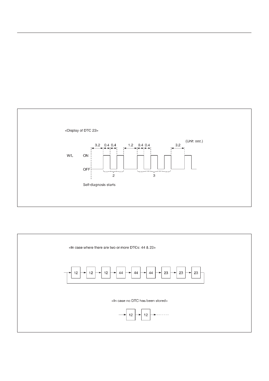
5. An example of DTC display

B05R100001

After displaying DTC 12 three times, one DTC after
another is displayed, starting with the most recent
one.  (However, display is discontinued after about 5
minutes.)

B05R100002

The DTC 12 is displayed repeatedly. (display is
discontinued after about 5 minutes after)

5A–39

BRAKE CONTROL SYSTEM

Chart B-1 With the key in the ON position (Before starting the engine).  Warning light (W/L)
is not activated.

Step

Action

Yes

No

1

Is W/L fuse disconnected?

Replace fuse.

Go to 

Step 5

Go to 

Step 2

2

Is W/L burnt out?

Replace W/L

bulb.

Go to 

Step 5

Go to 

Step 3

3

1. Turn the key off.
2. Disconnect coil integrated module connector (C-6).
3. Turn the key ON.

Is the check voltage between coil integrated module connector
(C-6) terminals 6 and 7 the battery voltage?

Go to 

Step 4

Repair harness

and connector.

Go to 

Step 5

4

Is there the continuity between coil integrated module connector
(C-6) terminals, 1 and 7 and body ground.

Check harness

for suspected

disconnection

No fault found:

Replace EHCU.

Go to 

Step 5

Repair harness

and connector.

Go to 

Step 5

5

Reconnect all components, ensure all components are properly
mounted.

Was this step finished?

Repeat the “Basic

diagnostic flow

chart”

Go to 

Step 5

Chart B-2 CPU Error (DTC 14 (Flash out) / C0271, C0272, C0273, C0284 (Serial
communications))

Step

Action

Yes

No

1

1. Turn the key off.
2. Disconnected coil integrated module connector.
3. Inspect coil integrated module ground.

Is there the continuity between the coil integrated module
connector terminals, 2 (C-5) and 7 (C-6) and body ground?

Go to 

Step 2

Repair the body

ground harness.

Go to 

Step 3

2

1. Turn the key off, connect the coil integrated module connector.
2. Erase the trouble code.
3. Turn Ignition off, then on, to perform system self-check.
4. If warning light remains on, display trouble codes once again.

Is the trouble code the DTC 14 (Flash out) / C0271, C0272,
C0273, C0284 (Serial communications)?

Replace EHCU.

Go to 

Step 3

Inspect in

accordance with

the DTC

displayed.

3

1. Reconnect all components, ensure all components are

properly mounted.

2. Clear diagnostic trouble code.

Was this step finished?

Repeat the “Basic

diagnostic flow

chart”

Go to 

Step 3

5A–40

BRAKE CONTROL SYSTEM

Chart B-3 Low or High Ignition Voltage (DTC 15 (Flash out) / C0277, 0278 (Serial
communications))

Step

Action

Yes

No

1

Is the battery voltage normal? (Battery capacity check)

Go to 

Step 2

Charge or

replace battery.

Go to 

Step 2

2

1. Turn the key off.
2. Disconnect coil integrated module connector.
3. Turn the key on.

Is the voltage between coil integrated module connector (C-6)
terminals 1 and 7, higher than 10V?

Check harness

connector for

suspected

disconnection

Fault found:

Repair, and

perform system

self-check

No fault found:

replace EHCU.

Go to 

Step 3

Repair harness or

connector.

Go to 

Step 3

3

1. Reconnect all components, ensure all components are

properly mounted.

2. Clear diagnostic trouble code.

Was this step finished?

Repeat the “Basic

diagnostic flow

chart”

Go to 

Step 3

Chart B-4 Excessive Dump Time (DTC 17 (Flash out) / C0269 (Serial communications))

Step

Action

Yes

No

1

Check for anything causing extended ABS activation, such as
locked brakes or an erratic speed sensor signal.

Was a problem found?

Repair or

Replace

Go to 

Step 2

2

1. The key turned off.
2. Replace EHCU.
3. Reconnect all components, ensure all components are

properly mounted.

Was this step finished?

Repeat the “Basic

diagnostic flow

chart”

Go to 

Step 2

Chart B-5 Excessive Isolation Time (DTC 18 (Flash out) / C0274 (Serial communications))

Step

Action

Yes

No

1

Check for anything causing extended ABS activation, such as
locked brakes or an erratic speed sensor signal.

Was a problem found?

Repair or

Replace

Go to 

Step 2

2

1. The key turned off.
2. Replace EHCU.
3. Reconnect all components, ensure all components are

properly mounted.

Was this step finished?

Repeat the “Basic

diagnostic flow

chart”

Go to 

Step 2

5A–41

BRAKE CONTROL SYSTEM

Chart B-6 G-Sensor Output Failure (DTC 21 (Flash out) / C0276 (Serial communications))

Step

Action

Yes

No

1

1. Turn the key off.
2. Replace EHCU.
3. Reconnect all components, ensure all components are

properly mounted.

Was this step finished?

Repeat the “Basic

diagnostic flow

chart”

Go to 

Step 1

Chart B-7 Brake Switch Failure (DTC 22 (Flash out) / C0281 (Serial communications))

Step

Action

Yes

No

1

Is the stop light actuated when the brake pedal is depressed?

Go to 

Step 2

Go to 

Step 4

2

1. Turn the key off.
2. Disconnected coil integrated module connector.

Is the check voltage between coil integrated module connector
(C-6) terminals 13 to 7 when brake pedal is depressed the battery
voltage?

Go to 

Step 3

Harness between

brake SW and

coil integrated

module is faulty.

Go to 

Step 6

3

Is the check that pins C-5 connector 2, and C-6 connector 7 have
good ground?

Check harness /

connector for

disconnection

Fault found:

Repair, and

perform system

self-check.

No fault found:

replace EHCU.

Go to 

Step 6

Repair.

Go to 

Step 6

4

Is stop light fuse normal?

Go to 

Step 5

Replace.

Go to 

Step 6

5

Is brake SW normal?

Abnormal

harness in stop

light circuit.

Repair the

harness.

Go to 

Step 6

Replace.

Go to 

Step 6

6

1. Reconnect all components, ensure all components are

properly mounted.

2. Clear diagnostic trouble code.

Was this step finished?

Repeat the “Basic

diagnostic flow

chart”

Go to 

Step 6


Content   ..  163  164  165  166   ..