Isuzu Amigo / Axiom / Trooper / Rodeo / VehiCross. Manual - part 164
5A–34
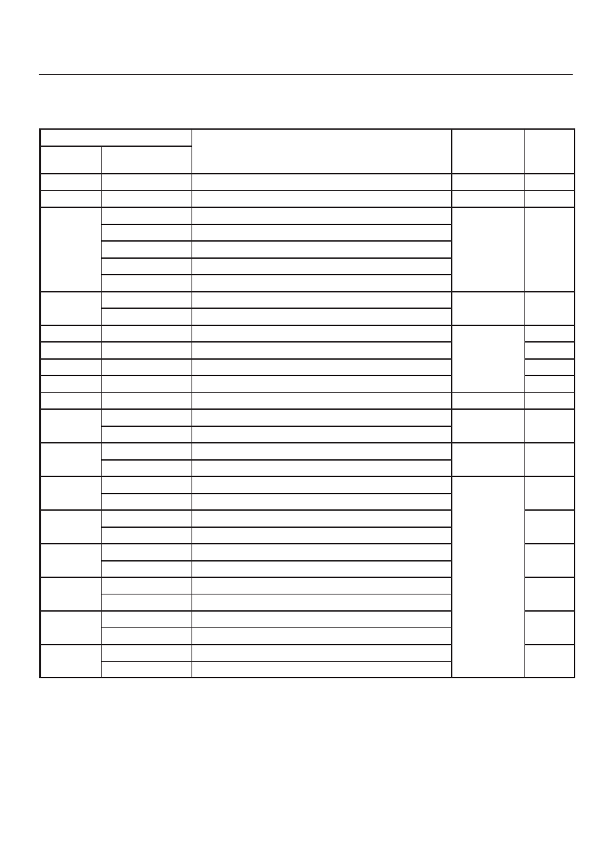
BRAKE CONTROL SYSTEM
Diagnostic Trouble Codes
Choose and trace an appropriate flowchart by the
numbers listed below to find fault and repair.
Code
Chart
Flash out
Serial
Communications
Diagnosis
Item
Chart
No.
12
—
—
—
—
13
C0285
2 WD Controller in 4WD Vehicle Controller
Wiring
B-8
14
C0271
RAM read/write error
C0272
ROM checksum error
Coil
C0270
ALU function error
Coil
Integrated
M d l
B-2
C0273
Inoperative isolation item
Module
C0284
Loop time overrun
15
C0277
Low ignition voltage
Wiring
B-3
C0278
High ignition voltage
Wiring
B-3
17
C0269
Excessive dump time
B-4
18
C0274
Excessive isolation time
Coil
Integrated
B-5
21
C0276
G-Sensor Failure
Integrated
Module
B-6
22
C0281
Brake switch Failure
B-7
24
C0282
Open or shorted 4
×
4 input signal (4WD only)
Wiring
B-8
32
C0267
Open motor circuit or shorted ECU output
Motor
B-9
C0268
Stalled motor or open ECU output
Motor
B-9
35
C0265
Open relay circuit
Relay
B-10
C0266
Shorted relay circuit
Relay
B-10
41
C0245
FL Open isolation solenoid or shorted ECU output
B-11
C0247
FL Shorted isolation solenoid or open ECU output
B-11
42
C0246
FL Open dump solenoid or shorted ECU output
B-12
C0248
FL Shorted dump solenoid or open ECU output
B-12
43
C0241
FR Open isolation solenoid or shorted ECU output
B-13
C0243
FR Shorted isolation solenoid or open ECU output
Solenoid
B-13
44
C0242
FR Open dump solenoid or shorted ECU output
Solenoid
B-14
C0244
FR Shorted dump solenoid or open ECU output
B-14
45
C0251
Rear Open isolation solenoid or shorted ECU output
B-15
C0253
Rear Shorted isolation solenoid or open ECU output
B-15
46
C0252
Rear Open dump solenoid or shorted ECU output
B-16
C0254
Rear Shorted dump solenoid or open ECU output
B-16